
Vehicle air conditioner with hot-gas heater cycle

a technology of heater cycle and vehicle air conditioner, which is applied in the direction of heating types, lighting and heating apparatus, instruments, etc., can solve the problem that the heating performance cannot be sufficiently improved in the heating mode, and achieve the effect of improving heating performance, efficient transmission and effective improvement of heating performan

Inactive Publication Date: 2006-04-18
DENSO CORP
View PDF17 Cites 19 Cited by
  • Summary
  • Abstract
  • Description
  • Claims
  • Application Information

AI Technical Summary

Benefits of technology

The present invention aims to improve the heating performance of a vehicle air conditioner in the hot-gas heating mode. It does this by using an accumulator to store liquid refrigerant and a heating device to heat the liquid refrigerant in the accumulator. This results in increased pressure of the refrigerant, which improves the heating performance of the air conditioner. The heating device can be a hot water pipe or an electric heater, and a pressure detection device can be used to control the operation of the electric heater. The invention also provides an improved water-proof structure for the electric heater.

Problems solved by technology

Accordingly, heating performance cannot be sufficiently improved in the heating mode.

Method used


Image

  • Vehicle air conditioner with hot-gas heater cycle
  • Vehicle air conditioner with hot-gas heater cycle
  • Vehicle air conditioner with hot-gas heater cycle

Examples


first embodiment

[0031](First Embodiment)

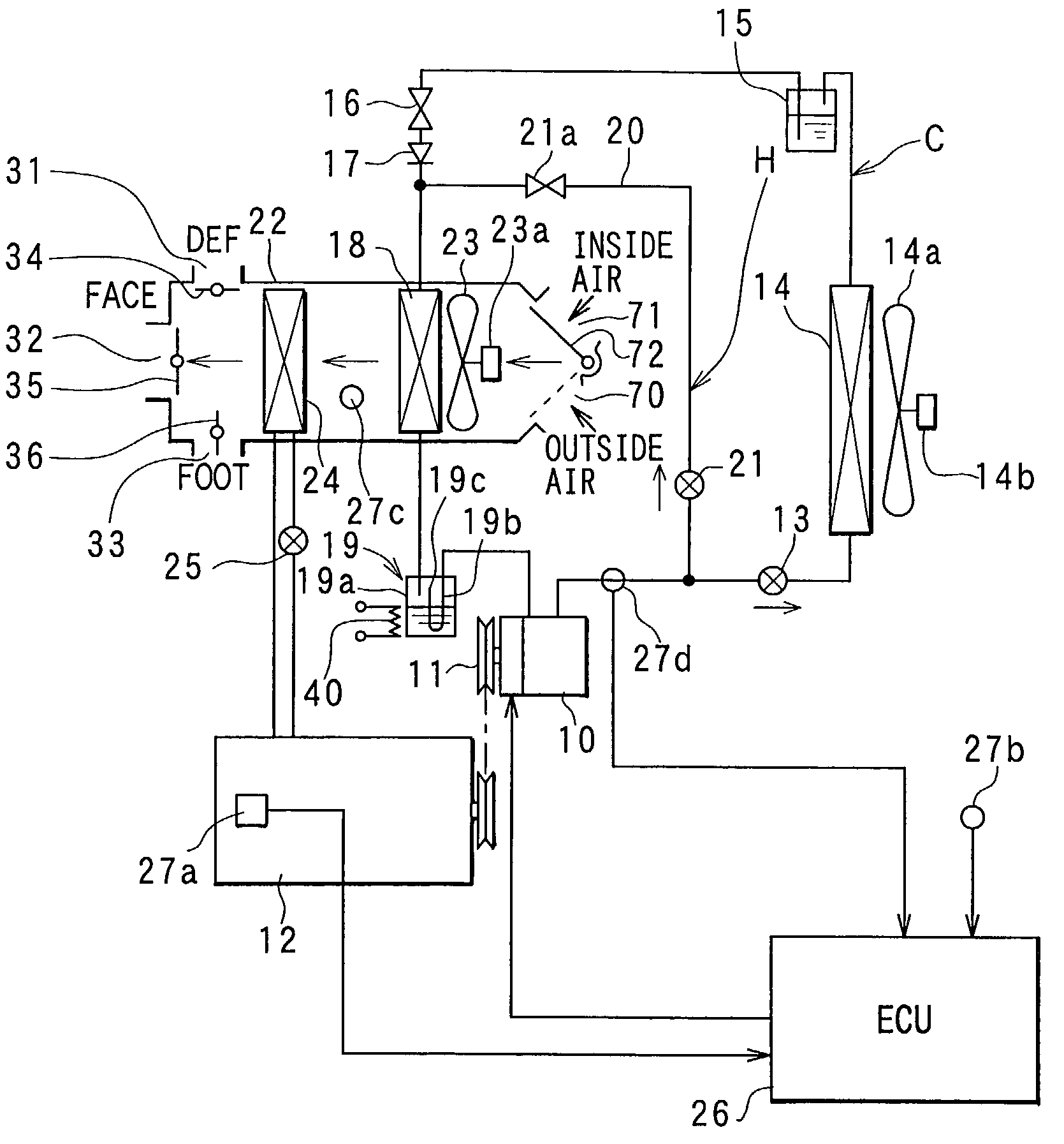
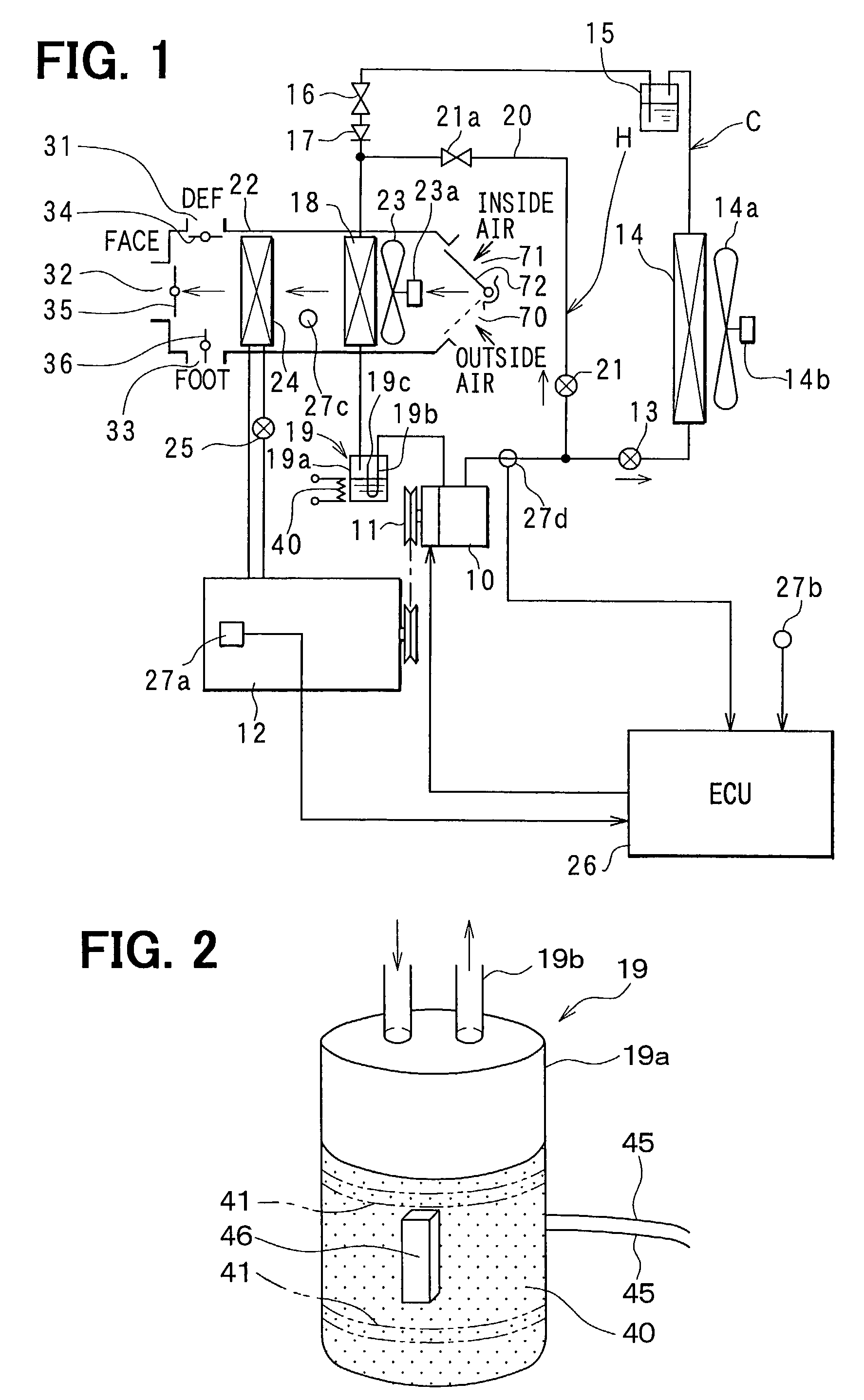
[0032]A vehicle air conditioner according to the first embodiment is shown in FIG. 1. A compressor 10 is driven by a water-cooled vehicle engine 12 through a solenoid clutch 11, and is constructed by a fixed-capacity swash-plate compressor, for example. A discharge port of the compressor 10 is connected to a condenser 14 through a cooling solenoid valve 13, and an outlet of the condenser 14 is connected to a receiver 15 for separating refrigerant into gas refrigerant and liquid refrigerant and for storing therein the separated liquid refrigerant. The condenser 14 is disposed in an engine compartment together with the compressor 10 and the like, and is an exterior heat exchanger where refrigerant is heat-exchanged with outside air blown by an electric cooling fan 14a. The electric cooling fan 14a is driven by a fan motor 14b. An outlet of the receiver 15 is connected to a thermal expansion valve 16 constructing a cooling decompression device, and an outlet of ...

second embodiment

[0059](Second Embodiment)

[0060]In the above-described first embodiment, the electric heater 40 is used as a heating device for heating the liquid refrigerant in the accumulator 19. In the second embodiment shown in FIG. 12, a hot water pipe 50, where engine-cooling water is circulated, is provided on the accumulator 19 at its lower portion in place of the electric heater 40. That is, liquid refrigerant in the accumulator 19 is heated by the hot water in the hot water pipe 50 as a heat source.

[0061]Specifically, three-way solenoid valves 51, 52 are added to the hot water circuit of the heating heat exchanger 24, and the hot water pipe 50 is connected to the solenoid valves 51, 52. Normally, the hot water pipe 50 is interrupted by the solenoid valves 51, 52 from the hot water circuit of the heating heat exchanger 24. If the determinations at steps S50, S60 in FIG. 5 are YES, that is, when the engine water temperature TW is low and the discharge pressure of refrigerant from the compres...


PUM


Abstract

A vehicle air conditioner selectively switches one of a cooling mode in which an interior heat exchanger of a refrigerant cycle is operated as an evaporator for cooling air, and a heating mode in which the interior heat exchanger is operated as a radiator for heating air. In the vehicle air conditioner, an accumulator, for separating gas refrigerant and liquid refrigerant from each other and for storing the separated liquid refrigerant therein, is disposed between an outlet of the interior heat exchanger and a suction port of a compressor. Further, the accumulator includes a heating device for heating the liquid refrigerant stored in the accumulator in the heating mode. Therefore, heating performance for heating air in heating mode can be efficiently improved.

Description

CROSS-REFERENCE TO RELATED APPLICATION[0001]This application is related to and claims priority from Japanese Patent Application No. 2001-346197 filed on Nov. 12, 2001, the content of which is hereby incorporated by reference.BACKGROUND OF THE INVENTION[0002]1. Field of the Invention[0003]The present invention relates to a vehicle air conditioner with a hot-gas heater cycle in which an interior heat exchanger is operated as a radiator by introducing hot gas refrigerant from a compressor directly into the interior heat exchanger. More particularly, the present invention relates to an accumulator having a heating device for heating refrigerant in the accumulator of the hot-gas heater cycle of the vehicle air conditioner.[0004]2. Description of Related Art[0005]A conventional vehicle air conditioner, disclosed in JP-A-11-42934, performs heating operation using a hot-gas heater cycle in a refrigerant cycle system. In this conventional vehicle air conditioner, when a temperature of coolin...

Claims


Application Information

Patent Timeline
Patent Type & Authority Patents(United States)
IPC IPC(8): F25B1/00B60H1/03B60H1/22B60H1/32F25B29/00B60H1/00F24F11/02F25B41/04F25B43/00
CPCB60H1/00914B60H1/3213F25B41/04F25B43/006B60H1/034F25B2700/21173B60H2001/00949B60H2001/325B60H2001/3255B60H2001/3261B60H2001/327B60H2001/3288F25B2400/0403F25B2400/0411F25B2500/28F25B2700/1931F25B2700/2104F25B2700/2106F25B2700/2113F25B41/20F25B41/24
Inventor TAKANO, YOSHIAKISHIMIZU, TOSHITAKA
Owner DENSO CORP
Learn More