
Optical disk, disk substrate, and drive

a technology of optical disks and substrates, applied in the direction of instruments, light beam reproducing, flat record carrier containers, etc., can solve the problems of deformation stress, small apparatus, deformation of recording and reproducing characteristics, etc., to improve the rigidity of the whole substrate, increase the frictional force, and speed up the effect of speed

Inactive Publication Date: 2006-04-11
HITACHT MAXELL LTD
View PDF35 Cites 29 Cited by
  • Summary
  • Abstract
  • Description
  • Claims
  • Application Information

AI Technical Summary

Benefits of technology

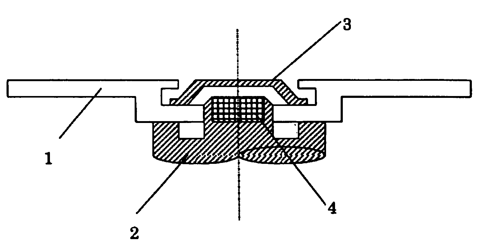
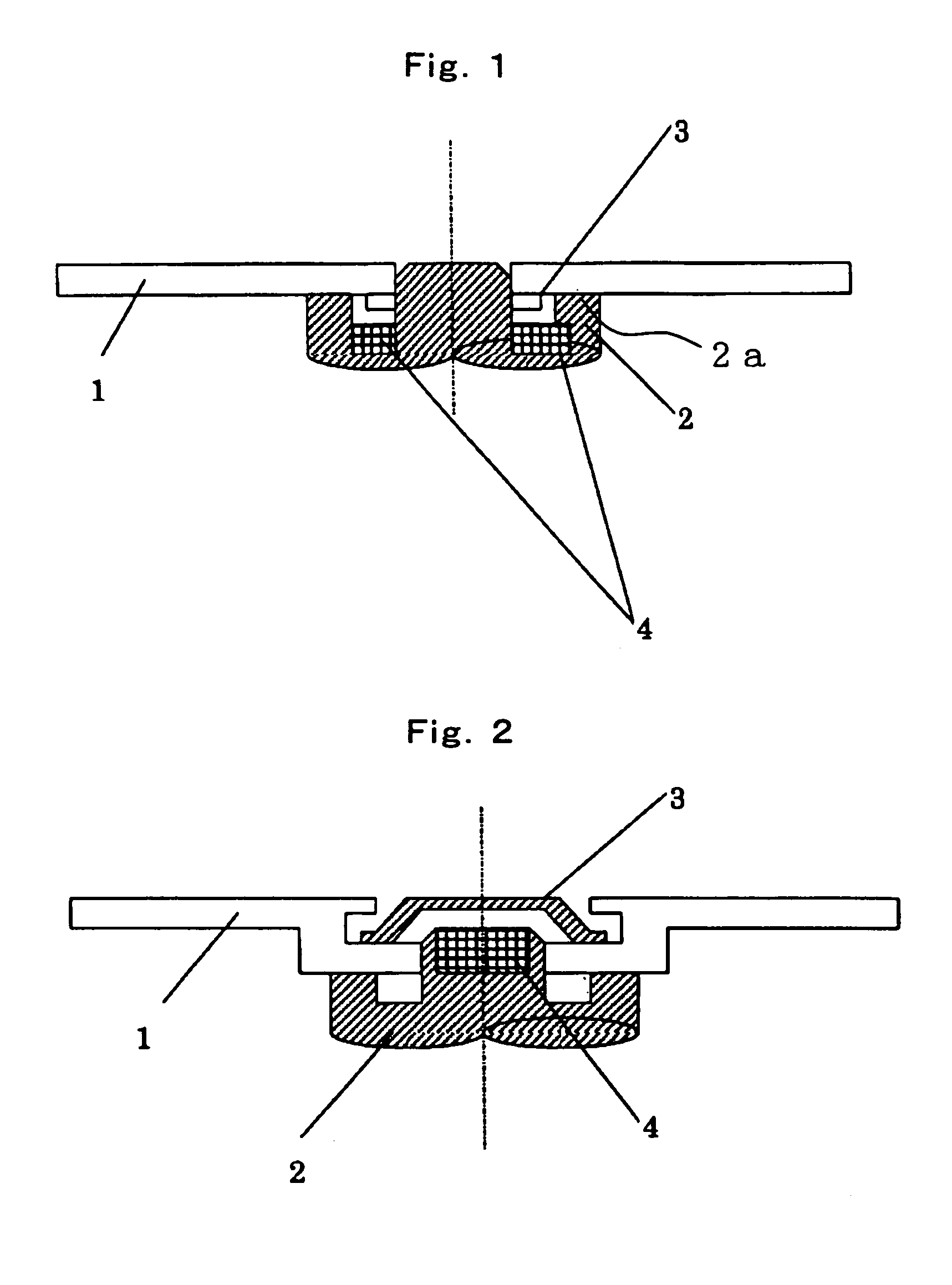
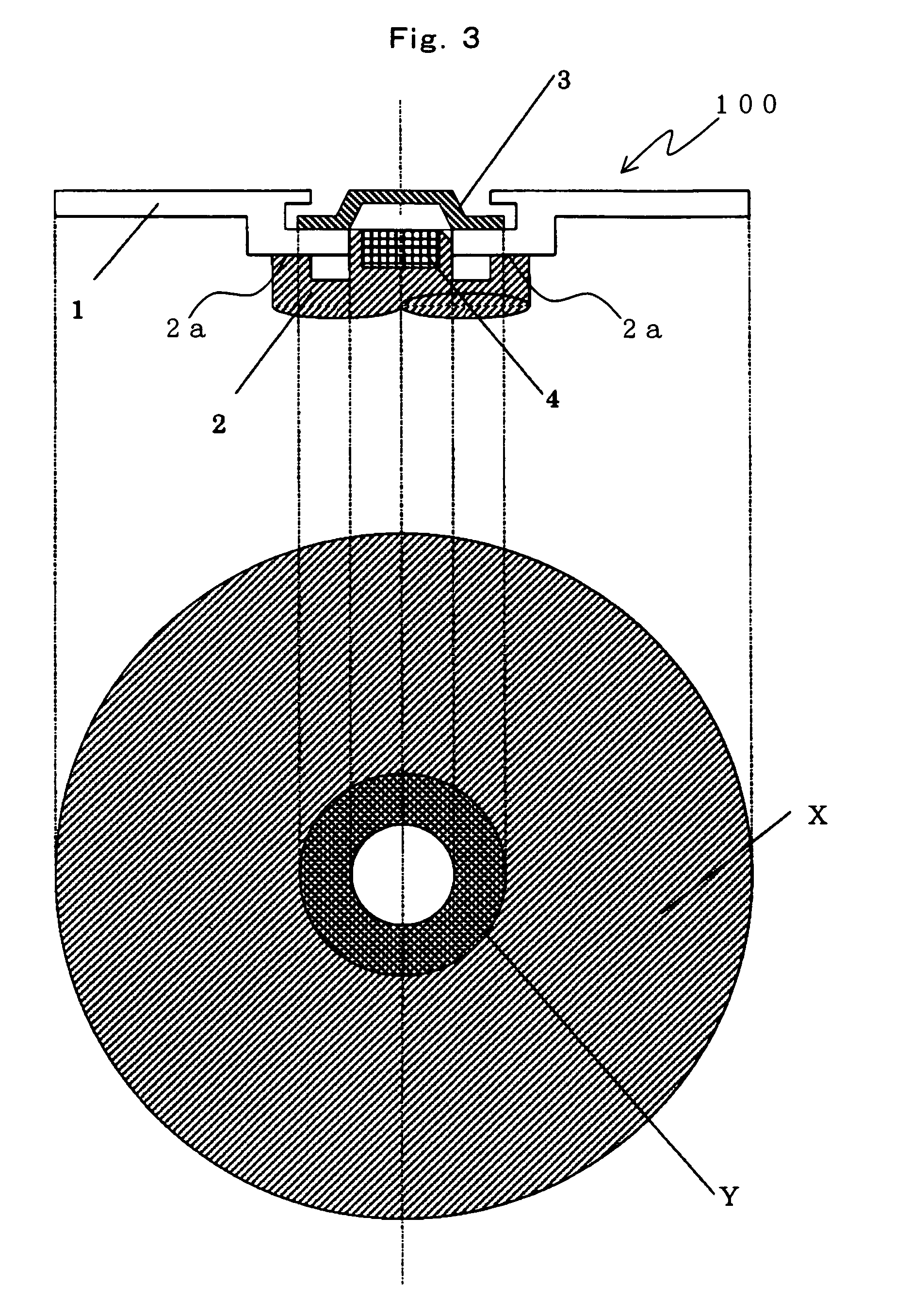
[0016]The optical disk according to the present invention is characterized in that the contact area Y between the magnetic clamping hub and the substrate is no less than 1.5% of the projected area X of the substrate. In other words, this disk is characterized by the ratio of Y to X (Y / X) being 0.015 or more. By determining the contact area between the substrate and the magnetic clamping hub so as to satisfy the above relationship, it is possible to increase the frictional force between the substrate and the hub, if the contact area between the substrate and the supporting surface of a spindle for rotating the optical disk is constant. Consequently, the camming and irregular rotation of the optical disk are suppressed even if it is rotated at high speed during the recordation and reproduction of information, since the force for holding the substrate is greater than conventionally. It is preferable that the ratio of the contact area Y to the projected area X of the substrate be higher for higher speed at which the optical disk rotates. Since the practical rotation speed is limited by the spindle motor for rotating the optical disk, it is more preferable that the ratio range from 2 to 7%.
[0045]A record disk that can be mounted on the driving apparatus according to the fifth aspect of the present invention may have a tilt mark, with which the signal detected by the tilt sensor varies with the tilt of the disk while the disk is rotating. This enables precise detection of the tilt of the rotating record disk, and can keep the disk horizontal.

Problems solved by technology

This system can make the apparatus small in comparison with the mechanical clamping system, but has the problem of retardation that the difference between the coefficients of thermal expansion of the plastic substrate and the hub develops a deforming stress in the substrate when the ambient temperature changes.
This retardation disturbs the states of polarization of the recording light and reproducing light for the magneto-optical disk, and may consequently degrade the recording and reproducing characteristics.
However, researches of the inventors revealed that, when a medium on the magnetic clamping system is rotated in a recording and reproducing apparatus at a speed higher than 720 rpm for a higher transfer rate, the apparatus vibrates, frequently causing tracking errors and / or data write / read errors.
Furthermore, the above-mentioned errors result from the camming and / or the disordered flow of air (turbulence) caused by the irregular rotation.
This makes the torque of the spindle apt to cause camming and deformation of the disk.
The camming and the deformation may make the disk rotation irregular and cause turbulence.
If the magneto-optical disk rotates at higher speed in a cartridge case, the disk rotation causes more turbulence in the cartridge.
In particular, because an optical disk including a thin substrate is apt to be charged, a remarkable amount of dust sticks to the disk.
In many actual cases, however, the angle between the recording surface of an optical record medium and the incident light is not right because of the substrate warpage caused when the medium is manufactured, setting errors of the optical system of a driving apparatus, and the disk distortion due to changes in environmental temperature and humidity.
It is therefore difficult to prevent the substrate from being warped and / or distorted.
This may prevent a desired record mark from being recorded.
If coma aberration is produced when information is reproduced, it is difficult to reproduce a recorded mark with sufficient resolution.
This makes the apparatus structure complex and costly.
This method also requires a certain amount of time for driving the optical system to make the optical axis of the incident light perpendicular to the medium surface.
This makes it difficult to manufacture a quickly responsive recording and reproducing apparatus.

Method used


Image

  • Optical disk, disk substrate, and drive
  • Optical disk, disk substrate, and drive
  • Optical disk, disk substrate, and drive

Examples


working example 1

[0125]A magneto-optical disk was produced which was similar in laminated structure to the disk 100 shown in FIG. 6. The disk 100 is a magneto-optical disk on the CAD system. The disk 100 is produced by the vacuum-spattering method, which includes the steps of forming on a transparent substrate 11 a first dielectric layer 12, a reproducing layer 13, an auxiliary magnetic layer 14, a second dielectric layer 15, a recording layer 16, a magnetic capping layer 17, a third dielectric layer 18 and a radiating layer 19 in order, and spin-coating a protective layer 20 on the top. The method for producing the disk 100 will be explained below in detail.

[0126]A substrate 11 was formed out of polycarbonate resin, which was injected and filled by the injection molding method. The substrate 11 was shaped as shown in FIG. 4A. In FIG. 4A, which is a cross section, as stated earlier on, the positions of the inner region 5a and outer region 6a and the difference in thickness between each of these regi...

working example 2

[0147]A magneto-optical disk was produced like Working Example 1 except that the contact area Y between the substrate and the magnetic clamping hub was changed to 2.30 cm2 (Y / X=0.020). The magneto-optical disk was housed in the same cartridge as was used for Working Example 1. The cartridge was then set in the recording and reproducing apparatus 71. The magneto-optical disk was then rotated at speeds between 0 rpm and 7,200 rpm. The rotational stability of the rotating disk and the occurrence of tracking errors and read errors were examined. The results of the examination are shown above in Table 1. As evident from the table, this magneto-optical disk was able to maintain stable rotational speeds within the whole range of rotation. No tracking error and no write / read error occurred. The magneto-optical disk is very suitable as a magneto-optical disk that can rotate within a range of rotation at high speed.

first embodiment

[0150]FIG. 19 schematically shows an optical record disk 190 including a substrate according to the third aspect of the invention and a mechanism for rotating the disk. The optical record disk 190 has a recording surface 191b in a predetermined region of an upper surface 191a of the substrate 191. The recording surface 191b can be irradiated with recording light or reproducing light so that information can be recorded or reproduced, respectively. The recording light or the reproducing light is incident on the underside of the optical record disk 190 in FIG. 19. The substrate 191 consists of a magnetic hub 192, a cylindrical hub holder 193 and a main body 194. The hub 192 is made of SUS material and put movably in the holder 193. The main body 194 extends radially outward from the top of the peripheral wall of the holder 193.

[0151]The substrate 191 takes the form of a disk, which has a diameter of 50 mm, and can be produced by injection molding. In FIG. 19, θ represents the angle of ...


PUM


Abstract

An optical disk 100 is provided with a hub 3 at the central portion of a substratel. A relationship Y / X≧0.015, preferably Y / X≧0.05 is satisfied where X is the projected area of the substrate 1 and Y is a contact area between the hub 3 and the substrate 1. As result, no slippage occurs between the hub 3 and the substrate 1 even when they are rotated at high speed than conventional. With this higher rotational speed, the data transfer rate is improved, and irregular rotation and the camming are suppressed, thereby reducing tracking errors and write / read errors.

Description

TECHNICAL FIELD[0001]The present invention relates to an optical disk chucked and rotating with a spindle, and to a substrate for an optical disk. The invention also relates to a driving apparatus for rotating an optical disk. In more detail, the invention relates to an optical disk having high data reliability and rotation stability even if it rotates at high speed, a substrate used for a record disk which can be kept horizontal while it is rotating, and a driving apparatus which can rotate a record disk while always keeping it horizontal.BACKGROUND ART[0002]Magneto-optical disks are widely used as external memories for computers etc. A mechanical clamping system and a magnetic clamping system are adopted for mounting magneto-optical disks on recording and reproducing apparatus. Unlike the mechanical clamping system, the magnetic clamping system needs no device for fixing a magneto-optical disk. As shown in FIG. 1, the magnetic clamping system involves supporting a substrate 1 on t...

Claims


Application Information

Patent Timeline
IPC IPC(8): G11B3/70G11B7/24G11B11/105G11B19/20G11B23/00G11B23/03
CPCG11B23/0035G11B19/2009G11B7/24G11B11/10584G11B23/0313
Inventor SHIMAZAKI, KATSUSUKEYAMAZAKI, YUUJIMIZUTANI, HIKARUMARO, TSUYOSHIOHTA, KENJITAKAGI, HIROYOSHITAKAHASHI, KATSUHIRO
Owner HITACHT MAXELL LTD
Learn More