
Video error concealment mechanism for block based video decompression

Inactive Publication Date: 2006-03-28
HITACHI LTD
View PDF11 Cites 24 Cited by
  • Summary
  • Abstract
  • Description
  • Claims
  • Application Information

AI Technical Summary

Benefits of technology

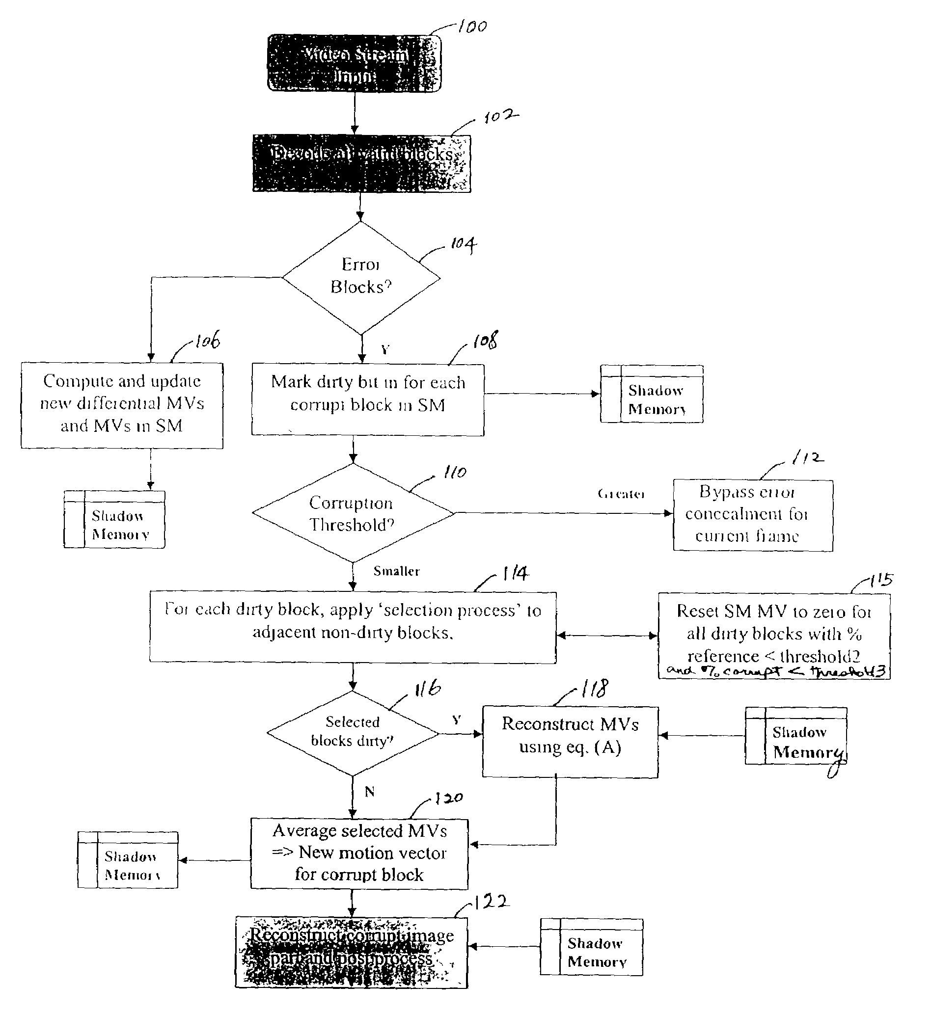
[0005]Embodiments of the present invention provide methods and apparatus for decoding digital video or motion picture signals with error concealment to prevent or minimize degradation of the picture quality. Motion video is characterized by temporal correlation. The present invention exploits such a correlation by reconstructing the nature of motion in frames and using the information from the reconstruction to estimate the location of a block as a result of motion. A shadow buffer is maintained that contains information used to predict a motion vector in case of a signal corruption. In specific embodiments, the information contained in the shadow buffer includes previously decoded motion vectors and the rate of change of motion. The rate of change of motion is determined for a given block by evaluating the difference between its motion vectors (MVs) in two successive frames: dx, dy=MV(x, y)t1−MV(x, y)t0, where t0 and t1 represent time for two successive frames. When corruption occurs, the method determines whether error concealment is needed according to a preset criterion. If so, motion vectors for the corrupt region are calculated using the information stored in the shadow buffer. Once the error concealment is complete, the “weight” or visual sensitivity of the restored block is decreased in order to reduce artifact effects such as those due to mismatch of “edges” at block boundaries. This is accomplished by a quantization mask employing the human visual system (HVS) concept.

Problems solved by technology

If the compressed motion picture signal includes an error which cannot be corrected by the error correcting ability of the decoder, the resulting motion picture output signal lacks a portion corresponding to the erroneous part of the compressed signal.

Method used


Image

  • Video error concealment mechanism for block based video decompression
  • Video error concealment mechanism for block based video decompression
  • Video error concealment mechanism for block based video decompression

Examples


Embodiment Construction

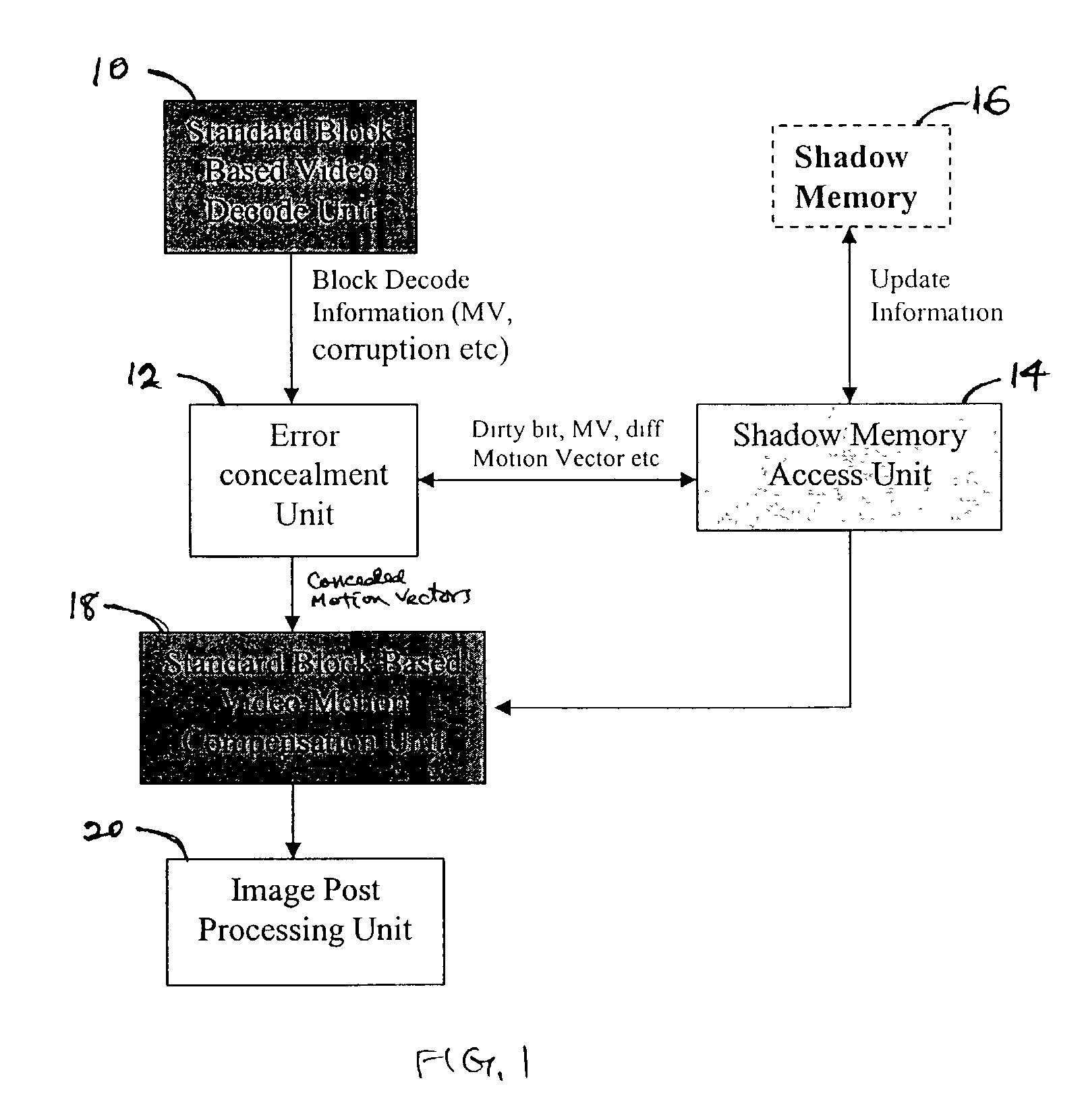
[0023]The present invention exploits the temporal correlation of motion video by reconstructing the nature of motion in frames and using the information from the reconstruction to estimate the location of a block as a result of motion. FIG. 1 shows a simplified block diagram of the system for decoding video signals using an error concealment scheme to prevent or minimize degradation of the picture quality due to corrupt blocks. The system includes a block-based video decoding unit 10 which may be a standard unit used to block-decode video signals. An error concealment unit or module 12 is provided to perform error concealment of corrupt blocks. A shadow memory access unit 14 allows access to a shadow memory or buffer 16 which stores information that can be used to predict a motion vector in case of a signal corruption. A standard block-based video motion compensation unit 18 is used to reconstruct image in the corrupt blocks. An image post-processing unit 20 performs post-processing...


PUM


Abstract

Embodiments of the present invention provide methods and apparatus for decoding digital video or motion picture signals with error concealment to prevent or minimize degradation of the picture quality. When corruption occurs, the method determines whether error concealment is needed according to a preset criterion. If so, motion vectors for the corrupt region are calculated using the motion vectors and rates of change of motion of current blocks in the current frame and / or old blocks in a previous frame according to a best matching block selection process. The method also determines if the “time” relative motion of content is small by defining a percentage use parameter. In some cases, once the error concealment is complete, the “weight” or visual sensitivity of the restored block is decreased in order to reduce boundary artifact effects. This is accomplished by a quantization mask employing the human visual system (HVS) concept.

Description

CROSS-REFERENCES TO RELATED APPLICATIONS[0001]Not ApplicableBACKGROUND OF THE INVENTION[0002]The present invention relates generally to methods and apparatus for decoding digital video or motion picture signals and, more particularly, to video error concealment for block-based video decompression.[0003]Video decompression of compressed signals is applicable in static recording media such as optical discs (e.g., DVD and VCD), in broadcast (e.g., via network), in streaming media (e.g., WMV and real video), and the like. Examples of video compression include MPEG (Moving Picture Experts Group) 2 and MPEG 4. In the MPEG systems, differences between pictures of the motion picture signal are determined to reduce redundancy in the time domain. These differences are subject to a discrete cosine transform (DCT) to reduce the redundancy in the spatial domain. Generally, a digital video signal coding apparatus first performs motion compensation for each of the pixel blocks (e.g., N×N pixels) w...

Claims


Application Information

Patent Timeline
IPC IPC(8): H04N7/12
CPCH04N19/139H04N19/895H04N19/86
Inventor TAVARES, CLIFFORD
Owner HITACHI LTD
Learn More