
Bistable magnetic device using soft magnetic intermediary material

a magnetic device and soft magnetic technology, applied in the field of magnetic devices, can solve the problems of increasing the amount of current used for switching memory cells, affecting the reliability of memory cell switching, increasing the amount of current used for mram devices,

Inactive Publication Date: 2006-03-28
MACRONIX INT CO LTD
View PDF14 Cites 47 Cited by
  • Summary
  • Abstract
  • Description
  • Claims
  • Application Information

AI Technical Summary

Benefits of technology

The invention describes a magnetic device that uses a soft magnetic material to switch its active layer. The device includes an electrically conductive structure, a layer of soft magnetic material, and a layer of magnetic material. The soft magnetic material is magnetized in a particular direction, which then magnetizes the active layer in the same direction. This results in a more efficient and effective switching of the magnetic device.

Problems solved by technology

However, switching of the memory cells is not always reliable.
This problem can typically be solved by increasing crystal anisotropy, coercivity or the aspect ratio of the memory cells, but these solutions can lead to another problem: the amount of current for switching the memory cells is also increased.
Increasing the amount of current increases the amount of power consumed by the MRAM device.
Increasing the amount of current also results in larger bit and word lines and write circuits to handle the higher currents, resulting is a larger, more expensive MRAM device.
Alternatively, the MRAM device could lose writing reliability by the electron migration effect.
Other problems with conventional MRAM arrays arise because of the need for ever-increasing levels of integration.
But as memory cell size is reduced, the magnetic field required to write to the cell is increased, making it more difficult for the bit to be written.
Again, larger writing currents can provide the required field strengths, but at the expense of larger conductors and write circuits.
If this happens repeatedly, the stored magnetic field of the adjacent cell can erode, and the information in the cell can be rendered unreadable.

Method used


Image

  • Bistable magnetic device using soft magnetic intermediary material
  • Bistable magnetic device using soft magnetic intermediary material
  • Bistable magnetic device using soft magnetic intermediary material

Examples


Embodiment Construction

[0018]A “soft” magnetic material is a magnetic material that magnetizes strongly in a feeble magnetic field. As used herein, a soft magnetic material is one having a coercivity of less than about 1 Oe (˜80 A / m), and a hard magnetic material is one having a coercivity of more than about 100 Oe (˜8000 A / m). Soft magnetic materials also generally have a higher permeability than hard magnetic materials, making them better for amplifying flux generated by electrical currents. As used herein, “magnetize” means to set the magnetization of a material. By itself, the term does not require that the material attain permanent magnetization.

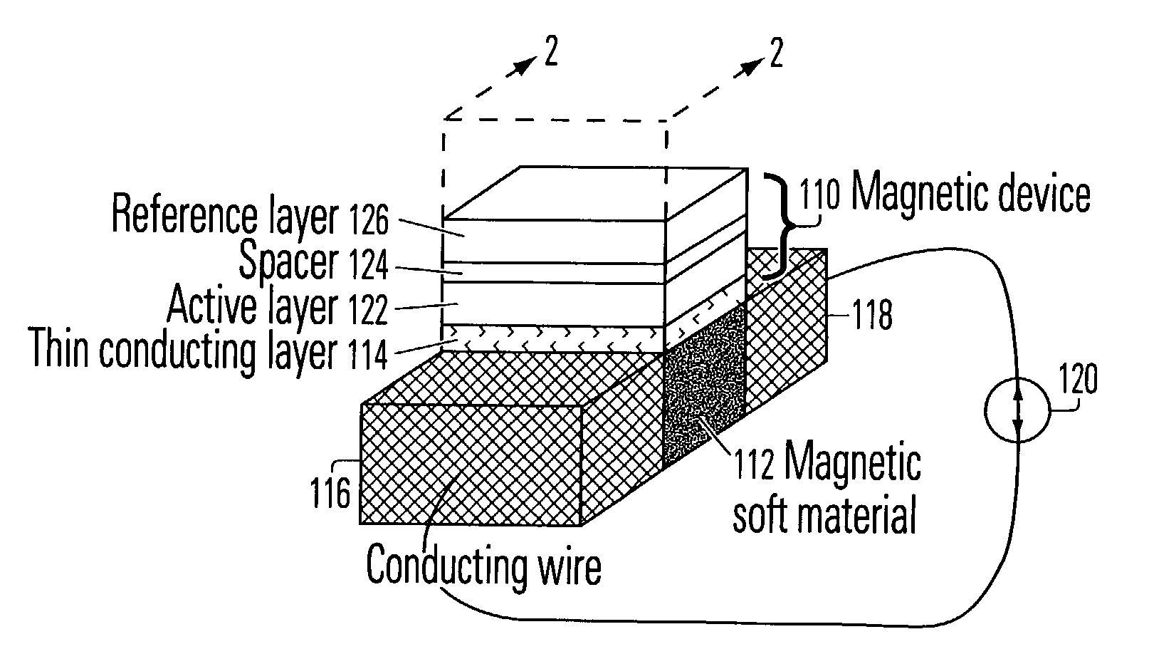
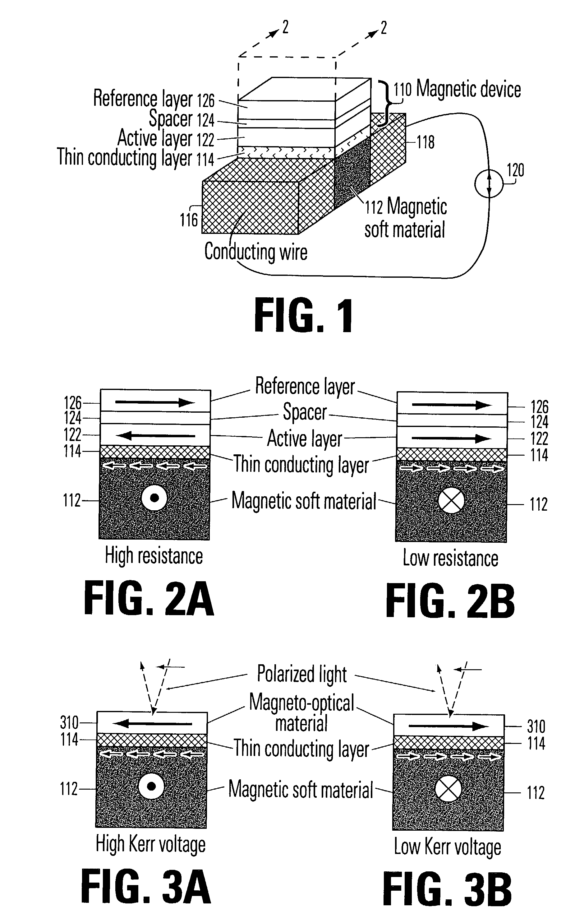
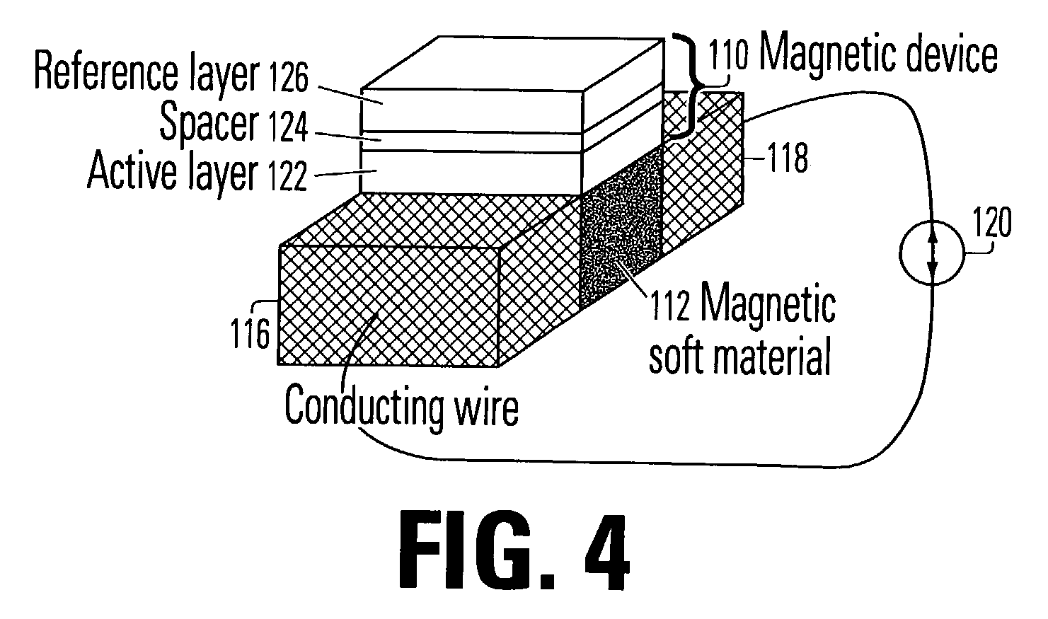
[0019]FIG. 1 is a symbolic diagram of a magnetic structure incorporating features of the invention. The structure includes a magnetic device 110 superposed over a soft magnetic material 112, separated by a thin conducting layer 114. The magnetic device 110 includes an active layer 122 which can be magnetized in either of two directions. It is disposed in suff...


PUM


Abstract

Roughly described, a magnetic structure includes an electrically conductive path for carrying current flow, a soft magnetic material with high permeability value in magnetic communication with the current flow so that it can be magnetized in either of two directions, and a magnetic device such as a magnetic random access memory cell, having an active layer that is quantum mechanically or magnetostatically coupled to the soft magnetic material. The soft magnetic material acts as an intermediary between the magnetic induction of the current flow and the magnetization of the active layer of the magnetic device to reduce the writing current.

Description

BACKGROUND OF THE INVENTION[0001]The invention relates to magnetic devices that exploit the dependence of a physical property, such as resistance, emission current or optical behavior, on the relative magnetization direction of the device. Such devices include, without limitation, magnetic memory cells, magnetic random access memories (MRAM), spin transistors, and near-field magneto-optical applications. More specifically, the invention relates to techniques for reducing the writing current required for the device to switch states, and increasing the magnetization stability and power gain of the device.[0002]A magnetic memory cell is a non-volatile memory that typically includes a portion of anisotropic magnetoresistive (AMR), colossus magnetoresistive (CMR), giant magnetoresistive (GMR) or magnetic tunnel junction (MTJ) material cooperating with electronic read and write circuits. The device employs a magnetic vector direction to store memory states, and a magnetoresistive effect f...

Claims


Application Information

Patent Timeline
Patent Type & Authority Patents(United States)
IPC IPC(8): G11C11/02G11C11/14G11C11/00G11C11/16
CPCG11C11/16
Inventor HO, CHIAHUACHEN, HSU SHUN
Owner MACRONIX INT CO LTD
Learn More