
Methods of charging lithium sulfur cells

a lithium sulfur cell and lithium sulfur technology, applied in secondary cell servicing/maintenance, cell components, greenhouse gas reduction, etc., can solve the problems of reducing the capacity of the cell, reducing the discharge voltage, and li/s cell sei formation is typically ineffective in preventing or minimizing lithium consuming reactions, etc., to achieve low self-discharge rate, high cathode utilization rate, and high charge-discharge efficiency

Active Publication Date: 2006-03-28
SION POWER CORP
View PDF33 Cites 43 Cited by
  • Summary
  • Abstract
  • Description
  • Claims
  • Application Information

AI Technical Summary

Benefits of technology

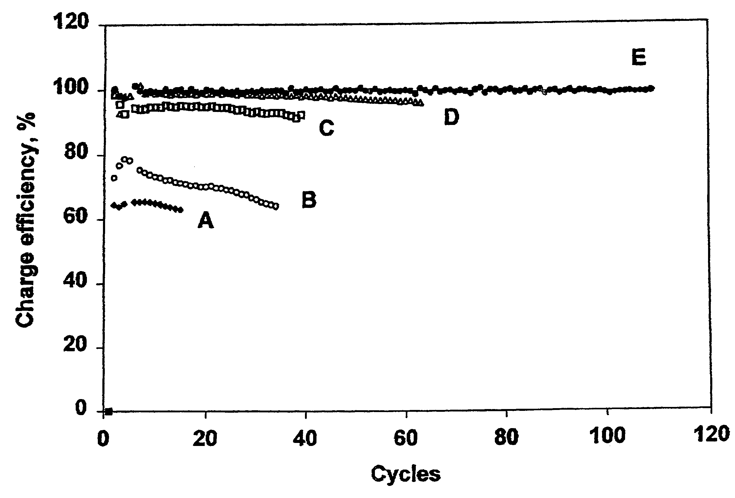
The use of N—O compounds in the electrolyte results in Li / S cells with significantly reduced self-discharge rates, increased sulfur utilization, and high charge-discharge efficiencies, allowing for longer cycle life and higher capacity retention, even at higher discharge rates.

Problems solved by technology

Undesirable properties of the SEI may include reduced discharge voltage and reduced capacity of the cell.
Soluble cathode reduction products from sulfur-containing cathode materials are known to be very reactive toward lithium anodes indicating that any SEI formed in Li / S cells is typically ineffective in preventing or minimizing lithium consuming reactions (these reactions are often termed lithium corrosion).
When a cell is recharged it may be unintentionally overcharged, which could lead to various undesirable reactions such as destruction of the cell electrolyte, corrosion of the current collectors, degradation of the cell separators, and irreversible damage to the positive or negative electrode.
Redox shuttles in electrochemical cells, however, have also been shown to have an undesirable impact on cell properties, such as leading to self-discharge.
This redox shuttle causes a continuous current flow in the cell, resulting in a depletion of the cell's stored capacity.

Method used


Image

  • Methods of charging lithium sulfur cells
  • Methods of charging lithium sulfur cells
  • Methods of charging lithium sulfur cells

Examples


example 1

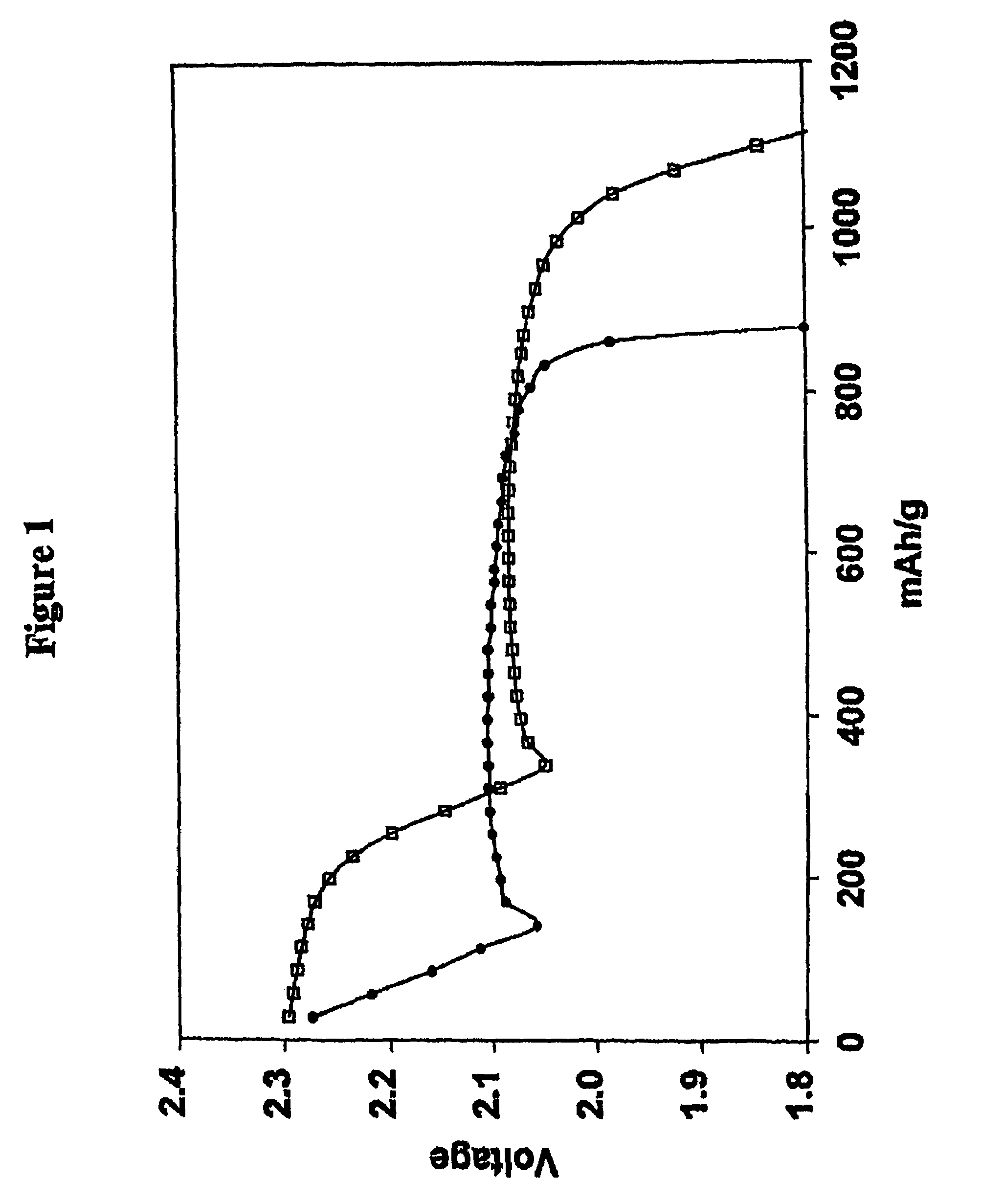
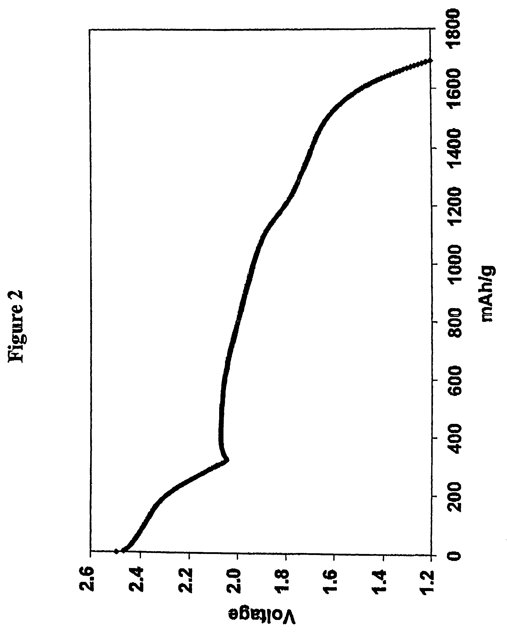
[0091]The electrolyte was that of Comparative Example 1 except that lithium nitrate at a concentration of 0.002 m was incorporated in the 0.5 m electrolyte solution of lithium imide in a 50 / 50 mixture of DOL and DME. In other words 0.002 moles of lithium nitrate (0.14 g) was added per Kg of the DOL / DME solvent (0.14 mg / g of solvent). Cycling of the cell was performed by the procedure of Comparative Example 1 with the results shown in Tables 2 and 3. Charge-discharge cycles were continued until the discharge capacity diminished to 900 mAh (874 mAh / g of sulfur; 52% utilization), which was 34 cycles and the accumulated capacity 33.7 Ah. 9 cycles were achieved before utilization fell below 60% (1005 mAh / g of sulfur).

example 2

[0092]The electrolyte was that of Comparative Example 1 except that lithium nitrate at a concentration of 0.1 m (6.9 mg / g of solvent) was incorporated in the 0.5 m electrolyte solution of lithium imide in a 50 / 50 mixture of DOL and DME. Cycling of the cell was performed by the procedure of Comparative Example 1 with the results shown in Tables 2 and 3. Charge-discharge cycles were continued until the discharge capacity diminished to 900 mAh (874 mAh / g of sulfur), which was 33 cycles and the accumulated capacity 37.1 Ah. 25 cycles were achieved before utilization fell below 60% (1005 mAh / g of sulfur).

example 3

[0093]The electrolyte was that of Comparative Example 1 except that lithium nitrate at a concentration of 0.2 m (13.8 mg / g of solvent) was incorporated in the 0.5 m electrolyte solution of lithium imide in a 50 / 50 mixture of DOL and DME. Cycling of the cell was performed by the procedure of Comparative Example 1 with the results shown in Tables 2 and 3. Charge-discharge cycles were continued until the discharge capacity diminished to 900 mAh (874 mAh / g of sulfur; 52% utilization), which was 46 cycles and the accumulated capacity 51.6 Ah. 39 cycles were achieved before utilization fell below 60% (1005 mAh / g of sulfur).


PUM

PropertyMeasurementUnit
voltageaaaaaaaaaa
termination voltageaaaaaaaaaa

Abstract

Disclosed is a method of charging a lithium-sulfur electrochemical cell wherein the lithium-sulfur cell comprises a cathode comprising an electroactive sulfur-containing material, an anode comprising lithium, and a nonaqueous electrolyte.

Description

TECHNICAL FIELD[0001]The present invention relates generally to the field of electrochemical cells and batteries, and to an electrolyte for use in an electrochemical cell. More particularly, this invention pertains to electrochemical cells where the cathode preferably comprises an electroactive sulfur-containing material and the anode preferably comprises lithium, and the cells deliver a high percentage of the theoretical discharge capacity, exhibit high charge-discharge efficiency, and / or show low self-discharge rates.BACKGROUND[0002]There has been considerable interest in recent years in developing high energy density batteries with lithium-containing anodes. Lithium metal is particularly attractive as the anode active material of electrochemical cells because of its light weight and high energy density, as compared, for example, to anode active materials such as lithium intercalated carbon anodes, where the presence of non-electroactive materials increases the weight and volume o...

Claims


Application Information

Patent Timeline
Patent Type & Authority Patents(United States)
IPC IPC(8): H02J7/04H01M4/38H01M4/58H01M4/60H01M10/44H02J7/00
CPCH01M4/38H01M6/168H01M10/0567H01M10/0569H02J7/0073H02J7/008Y02E70/40Y02B40/90H01M10/44H02J7/0071Y02E60/10H02J7/007182H02J7/00Y02B40/00Y02E60/13
Inventor MIKHAYLIK, YURIY V.
Owner SION POWER CORP
Learn More