
Radio terminal

a radio terminal and terminal technology, applied in the field of radio terminals, can solve the problems of degrading the receiving quality of the mobile terminal, the inability of the mobile terminal to receive the necessary number of base stations, and the weak signal from the base station, so as to speed up the speed of position measurement and reduce the capacity of the memory

Active Publication Date: 2006-03-21
MAXELL HLDG LTD
View PDF8 Cites 9 Cited by
  • Summary
  • Abstract
  • Description
  • Claims
  • Application Information

AI Technical Summary

Benefits of technology

[0011]Under the circumstances, it is an object of the present invention to provide a mobile terminal that can reduce the capacity of its memory while the position measurement is speeded up.
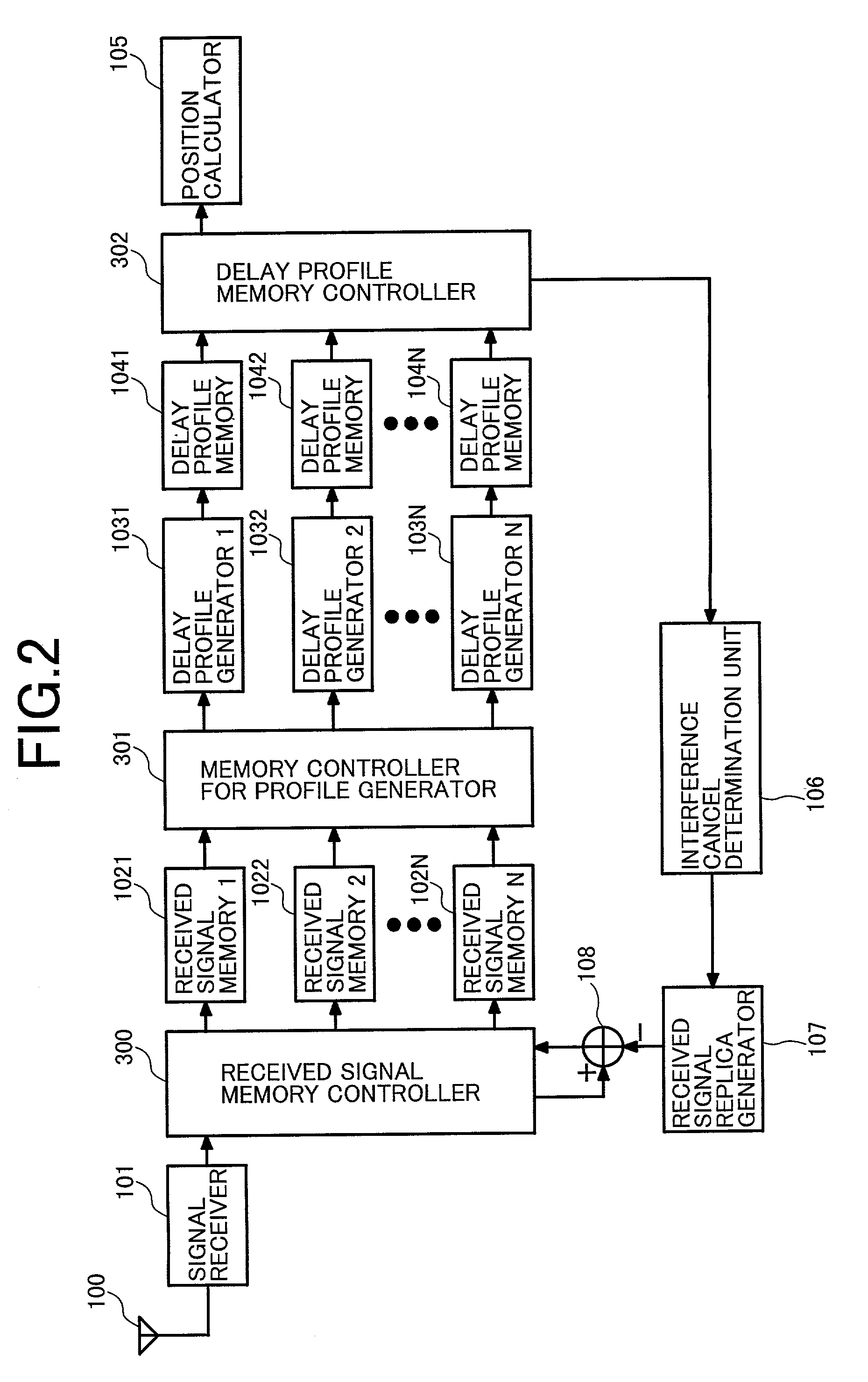
[0016]The radio terminal of the invention, because it is provided with a plurality of delay profile generating means such way, makes it possible to generate a plurality of delay profiles in parallel. This allows the position measuring time to be reduced and thereby improves the serviceability of position information.
[0017]Further, the radio terminal of the invention, because it is provided with correlation value retaining means for retaining a correlation value of each spreading code sequence, makes it possible to generate a replica of each delay profile with use of the correlation value so as to subtract the replica from the delay profile of another base station and cancel each interference component. This allows the received signal memory to be eliminated from the subject mobile terminal, and thereby reducing the hardware items, specifically the memory capacity in the mobile terminal provided with position measuring functions.

Problems solved by technology

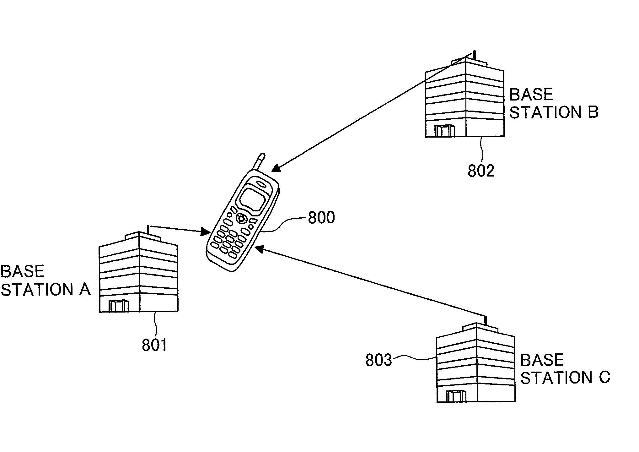
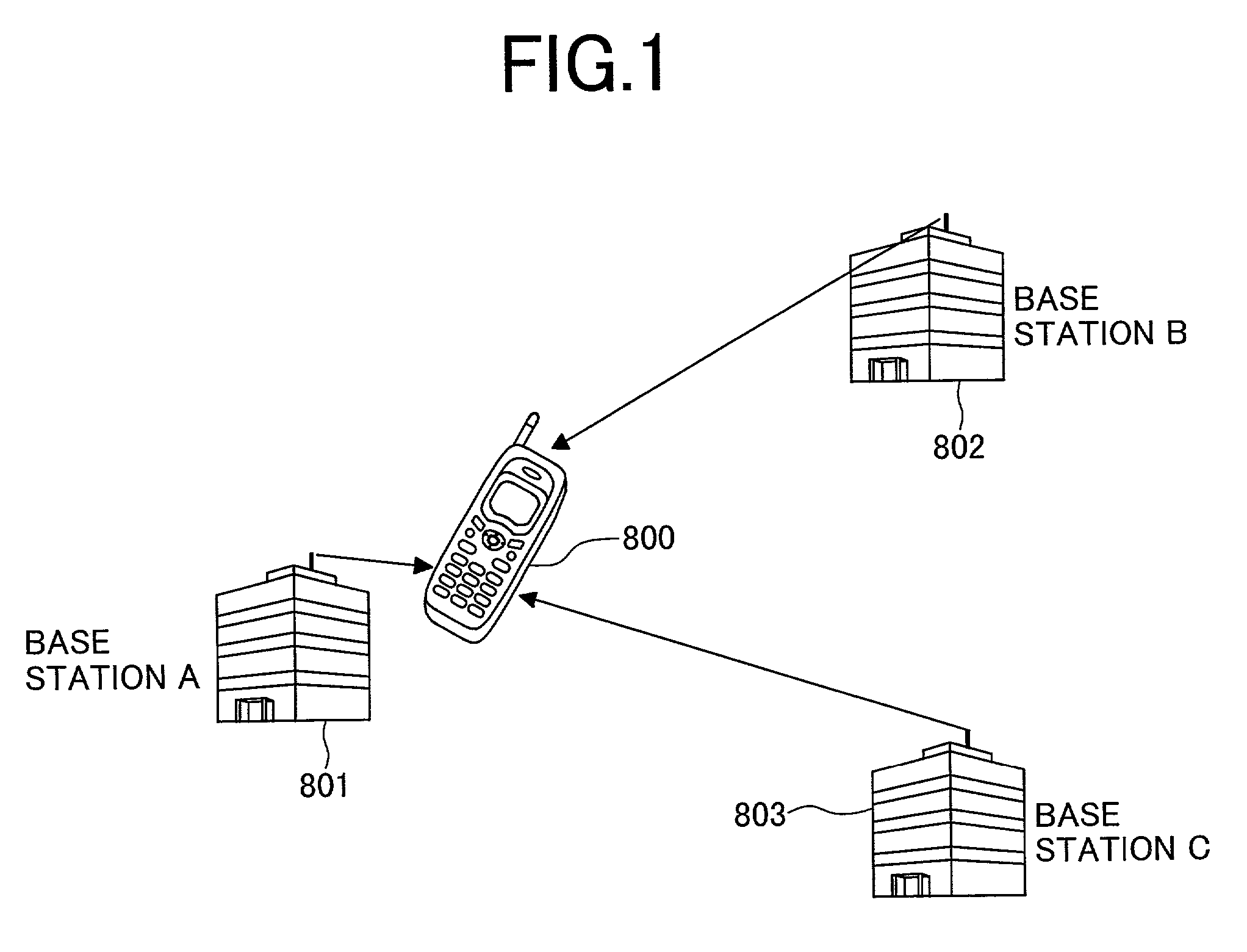
For example, when the mobile terminal positions very closely to a base station, the signal from the base station might be too strong.
The signal output from the base station often causes a so-called near-far problem that interferes signals output from other base stations, thereby the receiving quality of the mobile terminal is degraded.
If this near-far problem arises, the mobile terminal cannot receive signals from the necessary number of base stations to calculate its current position.
When it takes such a long time to generate a delay profile, the response of position measurement slows down, resulting in the degradation of the serviceability of position information.

Method used


Image

  • Radio terminal
  • Radio terminal
  • Radio terminal

Examples


first embodiment

[0036]FIG. 2 is a block diagram of a mobile terminal in the invention. In FIG. 2, the same reference numerals are used for the same functional items as those of the conventional mobile terminal shown in FIG. 12.

[0037]Signals received from base stations via the antenna 100 are sent to a signal receiver 101. The signal receiver 101 is composed of a radio part (receiver and transmitter), a base band processing part, etc. The radio part performs such receiving processings as amplification, frequency conversion, etc. of high and intermediate signals for cellular signals received from the base stations via the antenna 100 and the base band processing part performs such processings as demodulation, AD (Analog to Digital) conversion, etc. of base band signals to generate received signals. Received signals generated by the signal receiver 101 are written in the received signal memories 1021 to 102N sequentially via the received signal memory controller 300. The received signals written in th...

second embodiment

[0096]Such way, the mobile terminal in the second embodiment, provided with the correlation value memory 121 and the delay profile replica generator 120, can generate a replica of each delay profile with use of the correlation value stored in the correlation value memory 121 and subtract the replica from the delay profile of another base station to make interference cancellation. The mobile terminal can thus be configured without using any received signal memory, thereby the hardware scale, especially the memory capacity of the mobile terminal provided with positioning functions can be reduced and the mobile terminal can be reduced in both size and price.

[0097]FIG. 10 shows a block diagram of a mobile terminal in the third embodiment of the invention. In FIG. 10, the same reference numerals are used for the same functional items as those of the mobile terminals in the first embodiment (FIG. 2) and in the second embodiment (FIG. 7).

[0098]Signals received from base stations via the an...

third embodiment

[0106]Such way, the mobile terminal in this third embodiment, since it is provided with a plurality of delay profile generators 1031 to 103N, can generate a plurality of delay profiles in parallel, thereby the position calculating time can be reduced. In addition, the mobile terminal, since it is provided with the correlation value memory 121 and the delay profile replica generator 120, can generate a replica of each delay profile with use of a correlation value stored in the correlation value memory 121 and subtract the replica from the delay profile of another base station so as to make interference cancellation that eliminates signal interference from other base stations. It is thus possible to omit the conventional received signal memory to configure the mobile terminal. As a result, the hardware scale, especially the memory capacity of the mobile terminal provided with positioning functions can be reduced to improve the serviceability of position information. In addition, the m...


PUM


Abstract

A radio terminal that receives signals from a plurality of radio stations to calculate its current position has: interference canceling means for canceling each interference signal from the plurality of received signals; a plurality of delay profile generating means for generating delay profiles of the plurality of interference-canceled received signals with use of respective corresponding codes; and position calculating means for calculating its current position, which is a signal receiving point, with use of the plurality of delay profiles, whereby advantageously reducing the capacity of a memory mounted in the mobile terminal while the position calculation is speeded up

Description

BACKGROUND OF THE INVENTION[0001]1. Field of the Invention[0002]The present invention relates to a radio terminal that measures its current position with use of radio signals. More particularly, the invention relates to a radio terminal that can calculate a signal receiving point fast and reduce the chip area occupied by semiconductor elements used for the position measurement.[0003]2. Description of Related Art[0004]There have been proposed some techniques related to mobile communication systems; each technique enables respective mobile terminals to detect its current position with use of signals received from base stations in the mobile communication system. For example, JP-A 181242 / 1995 discloses a technique that measures a position of the subject mobile terminal with use of the position of each base station and a transmission delay time that differs among signals received from those base stations in a CDMA (Code Division Multiple Access) system.[0005]In the case where this mobil...

Claims


Application Information

Patent Timeline
IPC IPC(8): H04B1/00G01S5/14H04W64/00H04W72/08
CPCH04W64/00
Inventor TSUNEHARA, KATSUHIKOKUWAHARA, MIKIO
Owner MAXELL HLDG LTD
Learn More