
Wide bore high field magnet

Inactive Publication Date: 2006-03-21
FLORIDA STATE UNIVERSITY
View PDF21 Cites 34 Cited by
  • Summary
  • Abstract
  • Description
  • Claims
  • Application Information

AI Technical Summary

Benefits of technology

[0024]The invention meets the above needs and overcomes the deficiencies of the prior art by providing an improved 900 MHz wide bore NMR spectrometer magnet. Among the several objects and features of the present invention may be noted the provision of such magnet that provides increased field strength; the provision of such magnet that provides a higher spectrometer frequency; the provision of such magnet that permits a wide bore; and the provision of such magnet that is economically feasible.

Problems solved by technology

Due to the high stored energy of the 900 MHz system and the associated large magnetic forces, however, the production of a successful system is challenging.
The high field and large bore result in large mechanical stress in the coils and large magnetic stored energy.
Ferromagnetic welds cause field inhomogeneity.
This strategy is problematic in fabricating high field magnets because austenitic stainless steel is the preferred heat treatment material for bore tubes in Nb3Sn coils.
Bore tube removal is dangerous due to the risk of damaging the reacted Nb3Sn conductor and leads.
A major obstacle to producing a wide bore, high field magnet involves the relatively large mechanical stresses caused by the magnetic fields in the magnet.
Unfortunately, the materials normally found in high field superconductors are generally of low strength and the high temperature heat treatment and annealing to which such conductors are subject diminishes their strength even further.
Second, an axial force at each end of the coil toward the center results in a pressure at the midplane of the coil and tends to make the coil shorter.
This construction has strength in the radial direction, against the expansion of the hoops formed by the reinforcement winding, but can be weak in the axial direction, where any spaces between the turns in the reinforcement winding reduce the stiffness in the axial direction.
The so-called A15 high field superconductors, including Nb3Sn, are used to produce coils with the highest fields and forces but also tend to be the most brittle and subject to damage from mechanical stress.
Unfortunately, the fabrication process for this type of coil places restrictions on the manner in which the reinforcement can be included in the design.
This requirement is not severe for a small coil, but as the size of the coil increases for higher field magnets, this processing step becomes increasingly burdensome.
Furthermore, this situation makes it difficult to achieve a strong bond between the reinforcement and the coil winding because the reinforcement winding is being applied over a completed, epoxy impregnated winding.
Although applying the reinforcement winding over the conductor winding after heat treatment, but before epoxy impregnation, would solve the problem of the epoxy bond strength, the conductor in the coil after heat treatment is sufficiently brittle that the application of the reinforcement before impregnation of the winding would present a large risk to the integrity of the conductor.
Therefore, this option is not available.
Adequate quench protection presents another obstacle to producing high field magnets.
Superconducting magnets are subject to a mode of failure, known as “quench,” in which the stored energy is suddenly converted into heat accompanied by the presence of large electrical voltages.
If the region is of limited size, and all the energy of the magnet is deposited in the region, the energy density is high and the region will be likely to overheat.
The excessive heat and voltage during a quench can damage a magnet's windings.
Although systems are known for protecting the magnet from damage due to a quench fault condition, these conventional systems are not well-suited for high field superconducting magnets such as those desired for NMR.
Although this type of protection system may be suitable for superconducting magnets that operate at relatively high current in powered mode, an external dump of energy is not practical for NMR spectrometer magnets that operate at relatively low current in persistent mode.
In this instance, the local region will overheat and be damaged if enough energy is available in the magnet.
Unfortunately, use of the shunt path to spread the quench only works for coil sections that are thermally connected.
Yet another problem associated with conventional magnet design involves the leads of the superconducting coil.
Mechanical stress on the lead wire extending from a coil, resulting from Local Lorentz forces or relative motion between the coil and the surrounding support structure, for example, can damage the lead wire.
Moreover, certain known high field superconductors formed by a high temperature heat treatment are relatively brittle.
Thus, the amount of bending allowed by the superconductor is very limited after heat treatment.

Method used


Image

  • Wide bore high field magnet
  • Wide bore high field magnet
  • Wide bore high field magnet

Examples


Embodiment Construction

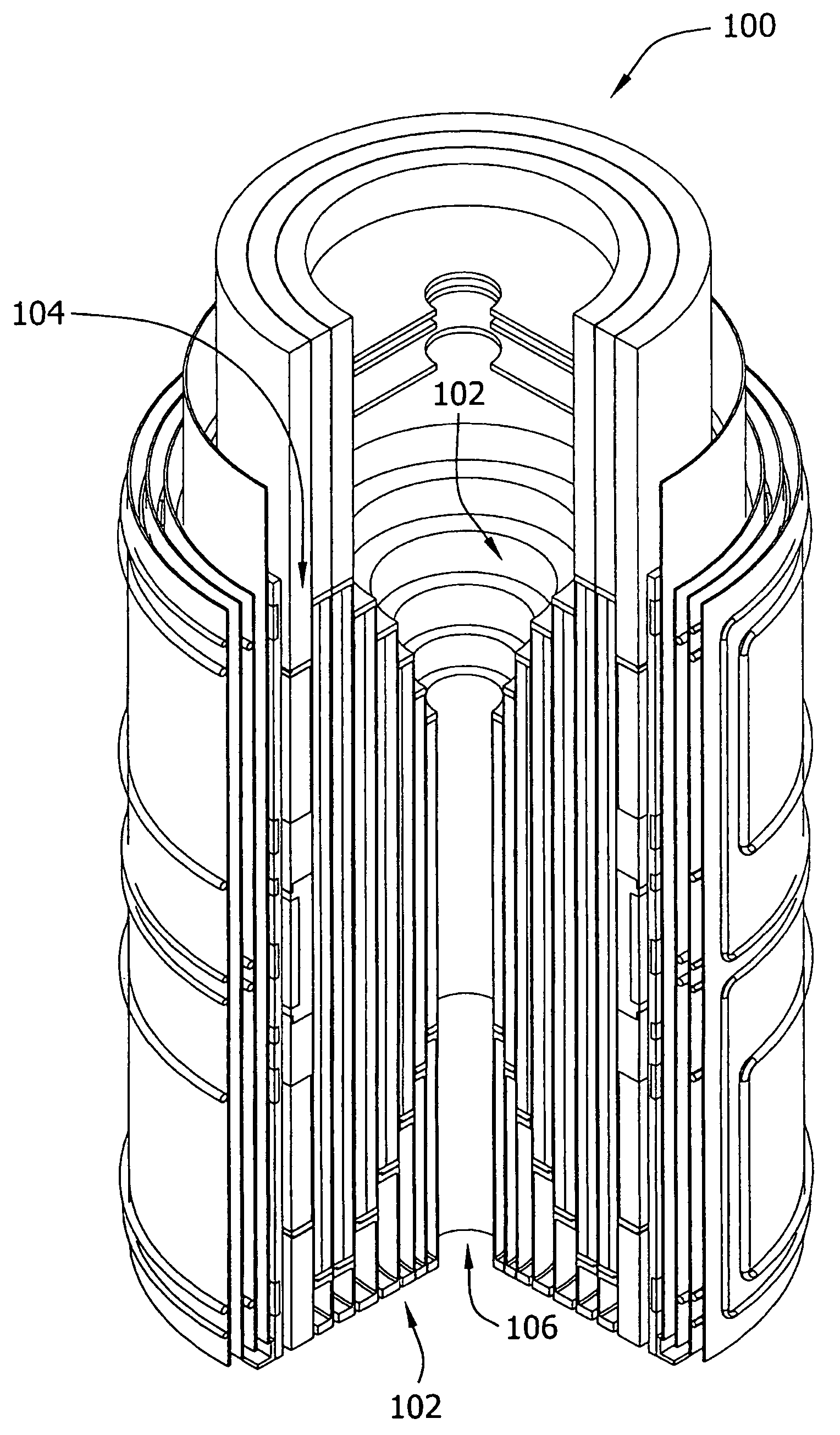
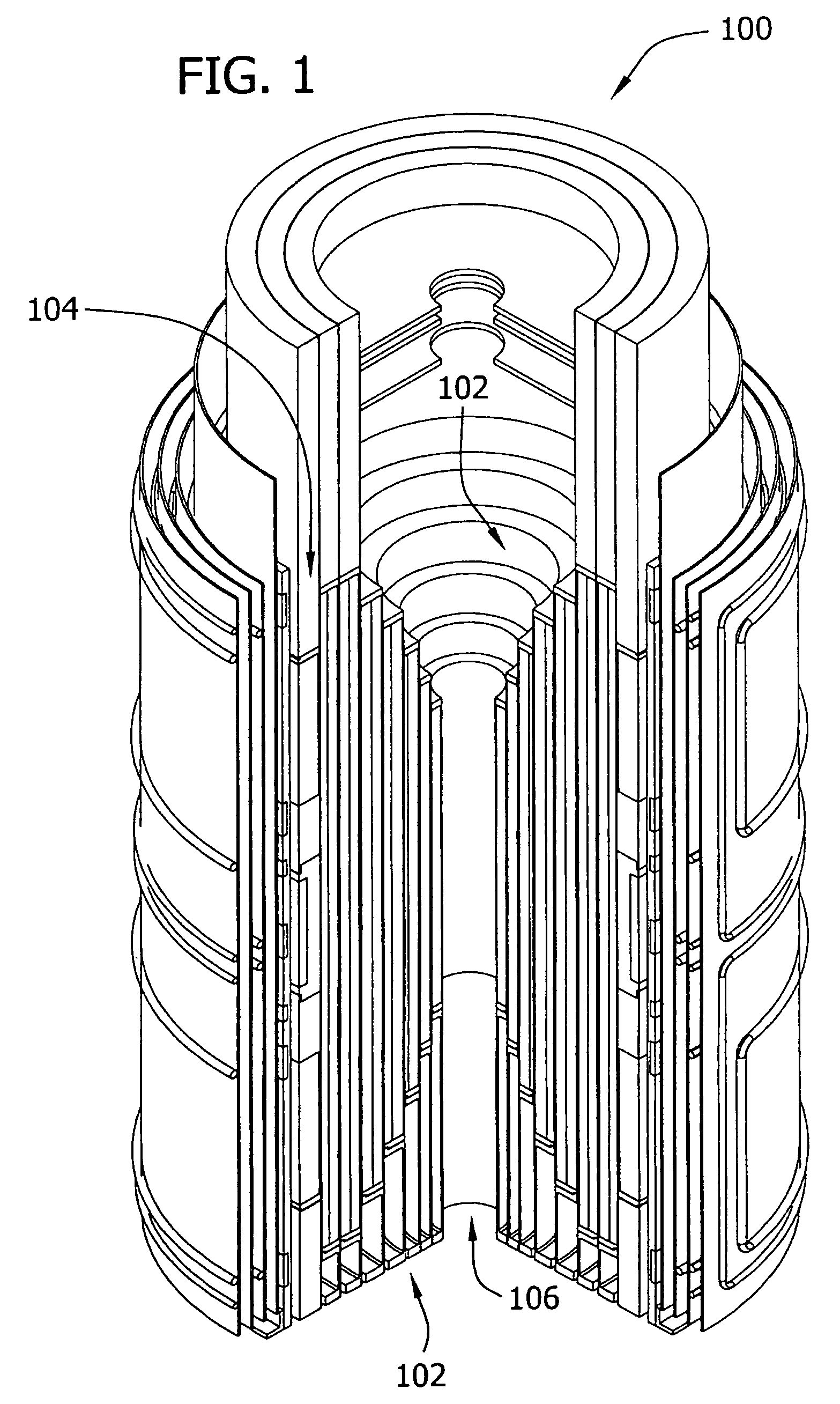
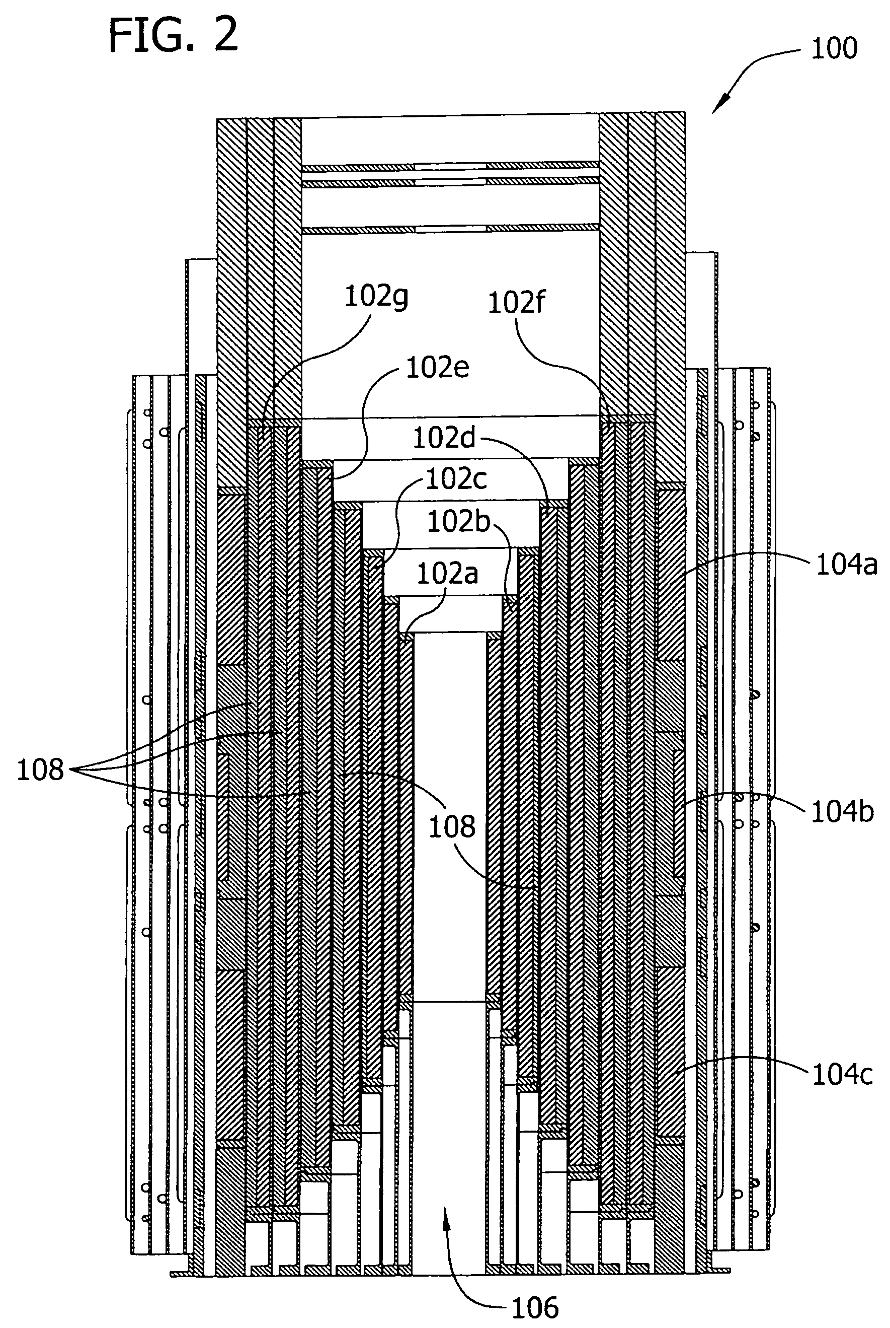
[0043]Referring now to the drawings, FIGS. 1 and 2 show a wide bore, high resolution NMR magnet 100. The magnet 100 preferably provides a spectrometer frequency of 900 MHz and a field of 21.1 T in operation within a cryostat (not shown) at approximately 1.8 degrees K. In general, magnet 100 has a plurality of coils 102 of high current density Nb3Sn and NbTi conductors in a set of epoxy impregnated long solenoids. Magnet 100 also includes a set of compensation coils 104 for uniformity. The high field and the relatively large bore, indicated generally at 106, cause large mechanical stress in the coils 102 in addition to large magnetic stored energy. Advantageously, magnet 100 includes lumped external reinforcement 108 for handling the stress in coils 102 and employs an active quench protection system 112 (see FIG. 5). The layout of magnet 100, including its individual coils 102, is shown in cross section in FIG. 2. The five inner most coils 102a–102e are preferably constructed with br...


PUM

PropertyMeasurementUnit
Lengthaaaaaaaaaa
Lengthaaaaaaaaaa
Widthaaaaaaaaaa

Abstract

A wide bore, high field superconducting magnet. The superconducting magnet has a plurality of superconducting coils impregnated with epoxy and nested within each other. An innermost one of the nested coils has a bore therethrough that defines a bore width of the magnet. The bore width is greater than approximately 100 millimeters. The nested coils are electrically connected in series and cooled to an operating temperature less than approximately 4 degrees K. The magnet also has external reinforcements on the coils that are applied prior to impregnating the coils with epoxy. An active protection circuit protects the coils in response to a quench in the magnet. The protection circuit includes heater elements positioned in thermal contact with the coils prior to impregnating the coils with epoxy. The magnet further has lead supports for supporting the lead wires with epoxy that extend from the coils.

Description

CROSS REFERENCE TO RELATED APPLICATION[0001]This application is a divisional application of application Ser. No. 09 / 668,992, filed Sep. 25, 2000 now U.S. Pat. No. 6,735,848, which claims the benefit of provisional application Ser. No. 60 / 156,081, filed Sep. 24, 1999, the entire disclosures of which are incorporated herein by reference.STATEMENT REGARDING FEDERALLY SPONSORED RESEARCH OR DEVELOPMENT[0002]This invention was made with Government support under Cooperative Agreement Nos. DMR-9016241 and / or DMR-9527035 awarded by the National Science Foundation. The Government has certain rights in this invention.BACKGROUND OF THE INVENTION[0003]The invention relates generally to a high field magnet and, particularly, to a high field superconducting magnet having a wide bore for use in a nuclear magnetic resonance (NMR) spectrometer.[0004]The technique of NMR has proven to be a powerful and unique tool for the study of complex molecular structures. High current density superconducting magn...

Claims


Application Information

Patent Timeline
IPC IPC(8): H01F5/00H01F6/00H01F41/04
CPCH01F6/00H01F41/048Y10T29/49014Y10T29/49071Y10T29/49361
Inventor MARKIEWICZ, W. DENISDIXON, IAIN R.SWENSON, CHARLES A.MARSHALL, W. SCOTTWALSH, ROBERT P.PAINTER, THOMASVAN SCIVER, STEVEN
Owner FLORIDA STATE UNIVERSITY
Learn More