Deep hole cutter

Active Publication Date: 2006-02-28
YUNITAKKU
View PDF13 Cites 23 Cited by
  • Summary
  • Abstract
  • Description
  • Claims
  • Application Information

AI Technical Summary

Benefits of technology

[0017]In view of the foregoing, the primary object of the present invention is to provide a deep hole cutter including a tool shank and a cutting head with two or more cutting edges, the tool shank and the cutting head being separate members connected strongly by threads or the like, the hole cutter being high in shaving dischargeability so as to be high in cutting efficiency.
[0019]Because each of the outer V-shaped discharge grooves of the tool shank and the cutting head is single, only one section in radial section is cut from the associated connecting part so that about ¾ of the connecting part can circumferentially continue. This makes the connecting parts strong enough to withstand cutting loads, so that they may hardly break, bend, twist or otherwise deform while the gun drill is drilling a hole. The shavings produced by the cutting edge facing the single discharge groove of the cutting head are discharged directly through the discharge grooves together with the coolant discharged from the outlet ports. In the meantime, the shavings produced by the cutting edge facing the discharge port flow together with the coolant through this port and the bypass passage into the discharge groove of the cutting head and are discharged through the discharge grooves. This makes the gun drill high in shaving dischargeability, thereby making it high in cutting efficiency.

Problems solved by technology

For rearrangement, it takes a long time to replace the long drill 30, so that the working efficiency is low.
When the carbide tip 35 is worn, it is not easy, but costly to regrind the tip.
This makes the costs even higher.
These discharge grooves would, however, reduce the threads 27a and 27b in area, greatly lowering the strength of the connection between the tool shank 21 and cutting head 22, so that the connection could not withstand cutting loads.
Accordingly, the screw connection between the cutting head 22P and the tool shank is very weak in strength, so that cutting loads are liable to break, bend, twist or otherwise deform the connection.

Method used


Image

  • Deep hole cutter
  • Deep hole cutter
  • Deep hole cutter

Examples


first embodiment

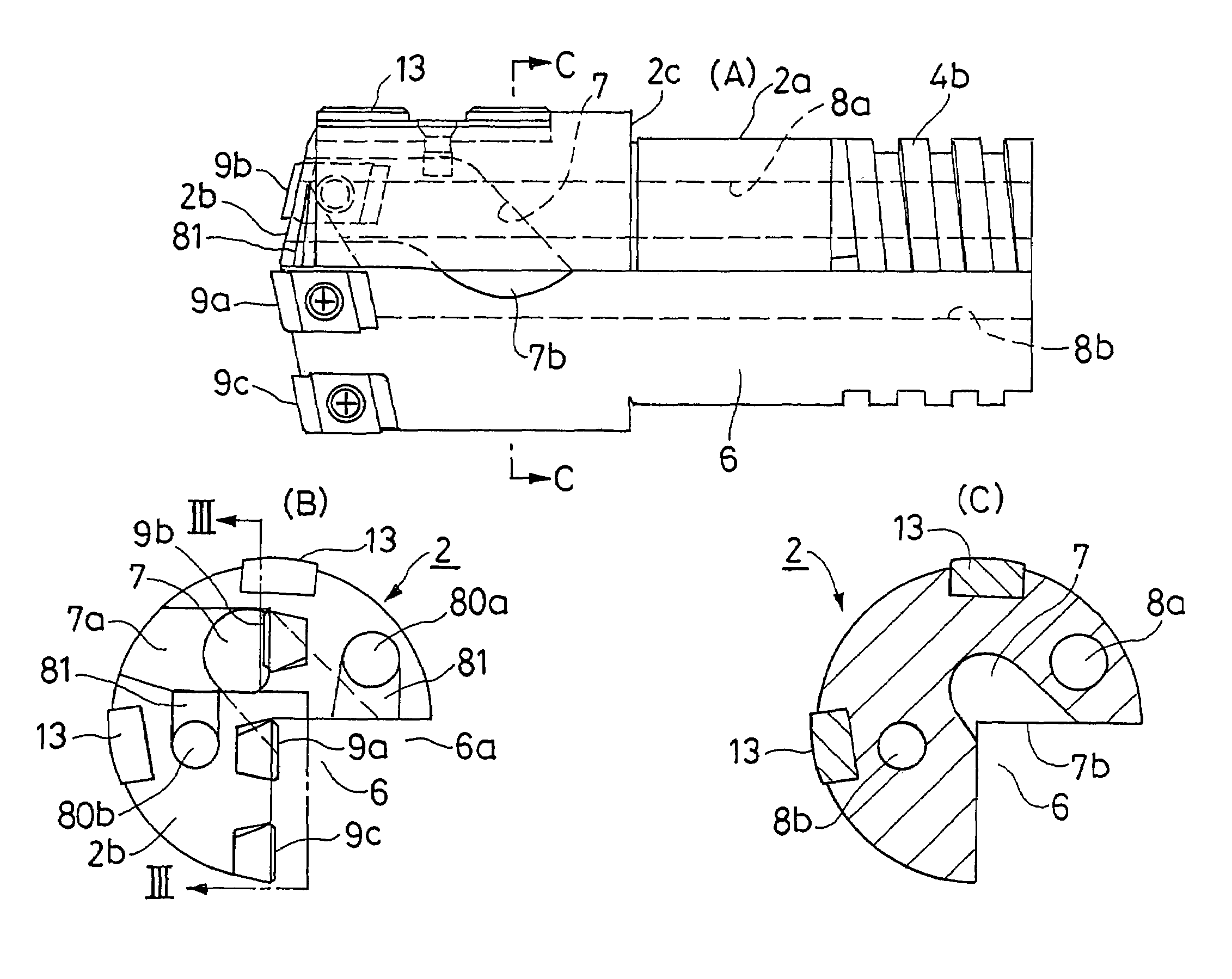
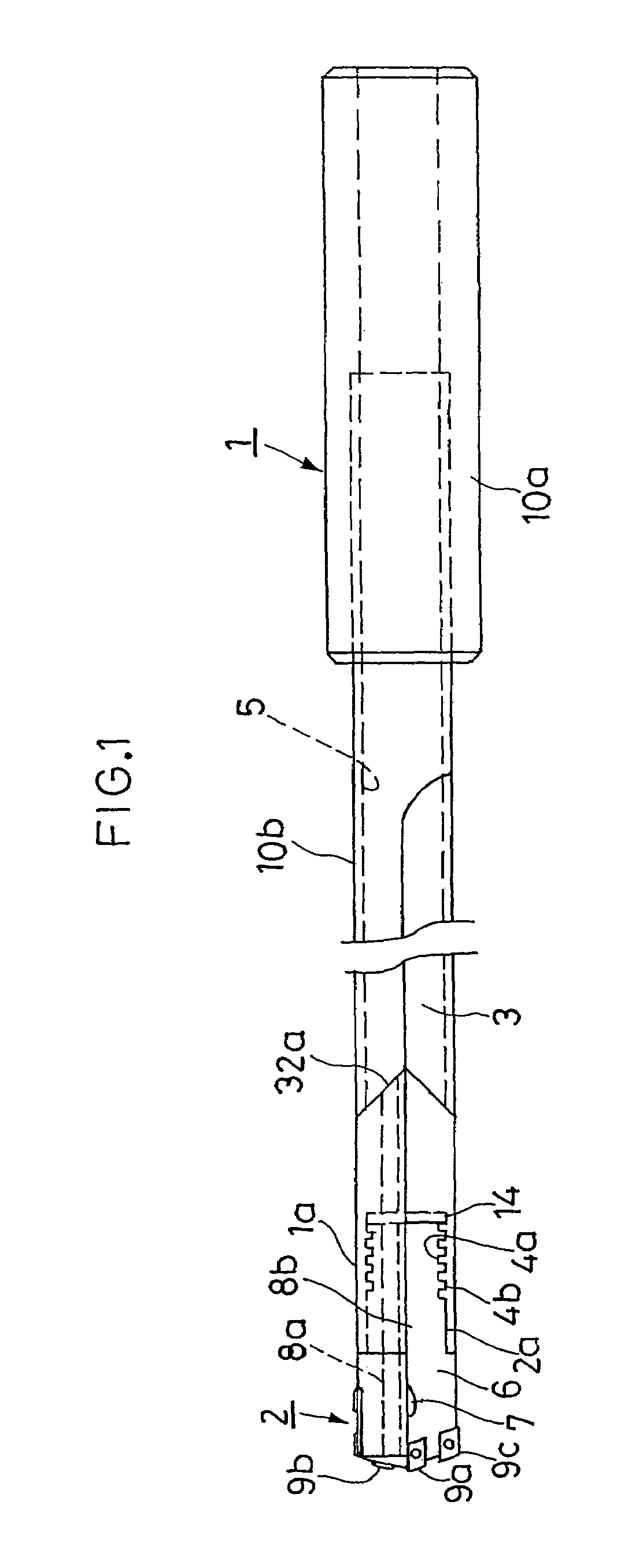
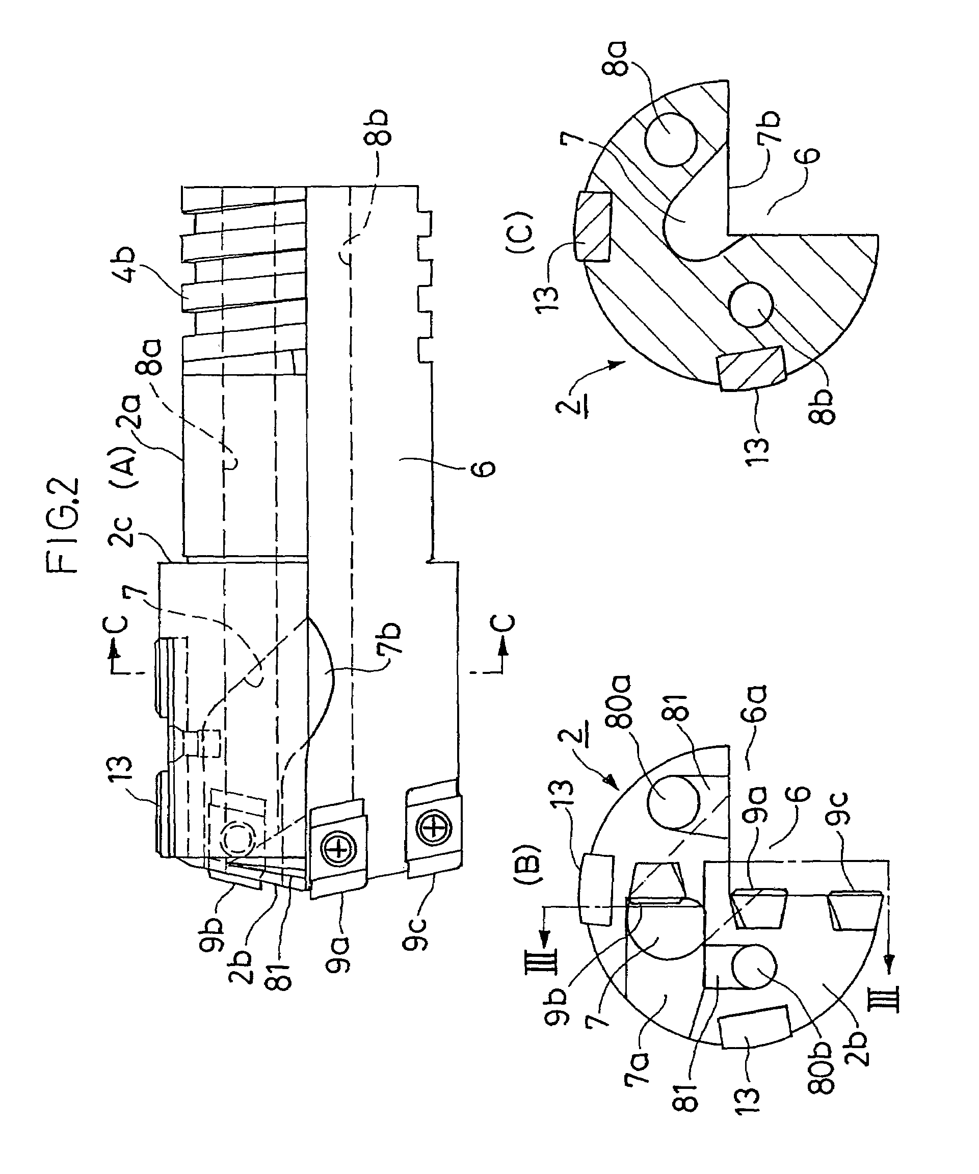
[0035]FIGS. 1–4 show a gun drill according to the present invention. As shown in FIG. 1, this gun drill consists of a tool shank 1 and a cutting head 2, which are coaxial with each other. The root of the cutting head 2 is screwed detachably into the front end of the tool shank 1.

[0036]The tool shank 1 consists of a cylindrical driver 10a, a tubular shaft 10b and a connector 1a, which consists of a rear part and a tubular front part. The cylindrical driver 10a is held by a chuck or the like to be rotated. The tubular shaft 10b is made of pipe material, and its root is fixed in the cylindrical driver 10a. The tubular shaft 10b has a V-shaped notch 32a formed in its front end, to which the rear end of the connector 1a is welded. The tubular front part of the connector 1a has a female square thread 4a formed near its bottom. The tool shank 1 has an outer axial discharge groove 3 V-shaped or fan-shaped in radial section. Both sides of the discharge groove 3 make an angle of about 90 degr...

third embodiment

[0054]FIGS. 8(A) and 8(B) show a gun drill according to the present invention.

[0055]In the first embodiment shown in FIGS. 1–4, the cutting head 2 is screwed into the tool shank 1.

[0056]As shown in FIGS. 8(A) and 8(B), the gun drill according to this embodiment includes a tool shank 1 and a cutting head 2, which are connected detachably by a connection 40. Each of the cutting head 2 and tool shank 1 has an axial coolant supply bore 8b formed in its center. The cutting head 2 and tool shank 1 have outer axial discharge grooves 6 and 3, respectively, which are roughly V-shaped in radial section. The cutting head 2 is fitted with a central carbide tip 9a, an intermediate carbide tip 9b and a peripheral carbide tip 9c, which are identical with those in the first embodiment. The cutting head 2 also has a discharge port (not shown) formed in it, which is identical with the port 7a in the first embodiment, and which is faced by the intermediate tip 9b. The cutting head 2 further has a bypa...


PUM

PropertyMeasurementUnit
Sizeaaaaaaaaaa
Efficiencyaaaaaaaaaa

Abstract

A deep hole cutter for a gun drill system includes a tool shank and a cutting head with two or more cutting edges. The tool shank and the cutting head are separate members connected strongly by threads. The shavings produced by the cutting edges can be discharged together with the coolant supplied through the hole cutter. The shaving dischargeability is improved for higher cutting efficiency.The tool shank 1 has one outer axial discharge groove 3. The cutting head 2 has one outer axial discharge groove 6 in linear alignment with the discharge groove 3. The cutting head 2 also has a discharge port 7a formed in its front end. The cutting head 2 further has a bypass passage 7 formed in it and extending between the discharge port 7a and the discharge groove 6. The cutting edges 9a and 9c face the discharge groove 6. The cutting edge 9b faces the discharge port 7a.

Description

BACKGROUND OF THE INVENTION[0001]1. Field of the Invention[0002]The present invention relates to a deep hole cutter such as a drill for application to a gun drill system.[0003]2. Description of the Related Art[0004]Gun drill systems, BTA systems, ejector systems, etc. are known as deep hole cutting systems. In general, gun drill systems that are simple in structure are used to cut deep holes that are relatively small in diameter.[0005]As shown in FIG. 12, a gun drill system includes a gun drill 30 consisting of a tubular tool shank 31 and a drill head 32. The tool shank 31 has an outer axial discharge groove 34 V-shaped in radial section. The drill head 32 is fixed to the front end of the tool shank 31. The interior of the tubular shank 31 serves as a supply passage 33. While the gun drill 30 is cutting a deep hole H in a work W,it produces shavings S in the hole H. In the meantime, a high pressure coolant C is supplied through the supply passage 33 and discharged from the front end...

Claims


Application Information

Patent Timeline
IPC IPC(8): B23B51/00B23B51/02B23B31/11B23B31/113B23B51/04
CPCB23B31/11B23B31/113B23B51/0493B23B2251/02B23B2251/422Y10T408/906B23B2251/56B23B2270/30Y10T408/9095Y10T408/905Y10T408/455B23B2251/50B23B51/063B23B51/00
Inventor NOMURA, TAKUJI
Owner YUNITAKKU
Why Eureka
Try Eureka