
Row-diagonal parity technique for enabling efficient recovery from double failures in a storage array

Active Publication Date: 2006-01-31
NETWORK APPLIANCE INC
View PDF67 Cites 142 Cited by
  • Summary
  • Abstract
  • Description
  • Claims
  • Application Information

AI Technical Summary

Benefits of technology

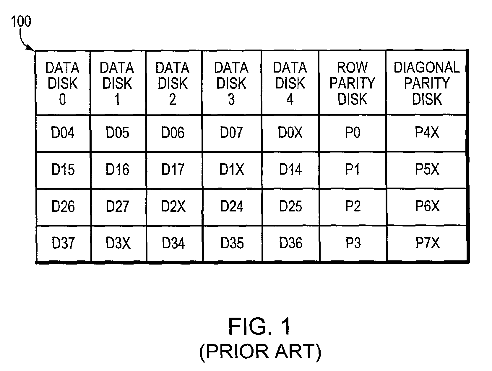
[0024]The present invention comprises a “row-diagonal” (R-D) parity technique that reduces overhead of computing diagonal parity for a storage array adapted to enable efficient recovery from the concurrent failure of two storage devices in the array. The R-D parity technique is preferably used in an array comprising a number n of storage devices, such as disks, including a row parity disk and a diagonal parity disk, wherein n=p+1 and p is a prime number. The disks are divided into blocks and the blocks are organized into stripes, wherein each stripe comprises n−2 rows. The blocks of the rows selected to form a stripe are typically contiguous on each disk, although this not a requirement of the invention. The diagonal parity disk stores parity information computed along diagonal parity sets (“diagonals”) of the array. The blocks in the stripe are organized into n−1 diagonals, each of which contains n−2 blocks from the data and row parity disks, and all but one of which stores its parity in a block on the diagonal parity disk. As a result, the novel R-D parity technique provides a uniform stripe depth and an amount of parity information equal to two disks worth, which is the minimum amount required to allow reconstruction from any two disk failures.
[0026]Advantageously, the inventive technique minimizes the computation load to compute parity stored in the array during failure-free operation. The technique also minimizes the overhead of parity computation, and requires less computation compared to conventional schemes, such as EVENODD, for a given number of data disks. The inventive R-D parity technique speeds recovery by minimizing the total amount of computation that must be done to recover missing data. In addition, since the invention may be implemented using a concentrated parity technique, where row parity blocks are all stored on the same disk, data disks may be incrementally added to the array without reformatting or recalculating the existing parity information. The only restriction to the addition of data disks to the array is that the maximum number of disks that can be used in the array must be decided beforehand (a priori). This restriction is due to the use of diagonals and their lengths depending upon the stripe depth. The difference between the number of actual disks present and the maximum number of disks in the array is filled with “imaginary” disks that contain only zero-valued data.

Problems solved by technology

In the operation of a disk array, it is anticipated that a disk can fail.
Data can be lost when one or more disks fail, making it impossible to recover data from the device.
Mirroring is an expensive solution in terms of consumption of storage resources, such as disks.
Backup does not protect data modified since the backup was created.
However, if two disks fail concurrently within a parity group, then an unrecoverable loss of data is suffered.
Failure of two disks concurrently within a parity group is a fairly common occurrence, particularly because disks “wear out” and because of environmental factors with respect to the operation of the disks.
A double failure typically arises as a result of a failure of one disk and a subsequent failure of another disk while attempting to recover from the first failure.
If the storage system is busy serving requests, the elapsed time for reconstruction increases.
However, having small parity groups is expensive, as each parity group requires an entire disk devoted to redundant data.
Another failure mode of disks is media read errors, wherein a single block or sector of a disk cannot be read.
However, if one disk has already failed, then a media read error on another disk in the array will result in lost data.
Lower cost disks typically have a shorter lifetime, and possibly a higher failure rate during their lifetime, than higher cost disks.
Yet, as noted, such an arrangement does not have a location for storing the parity block for all the diagonals.
Although the EVENODD technique is optimal in terms of the amount of parity information, the amount of computation required for both encoding and decoding is only asymptotically optimal.
That is, the p−1 blocks in a stripe are not enough to hold the p parity blocks generated from the p diagonals.
To overcome this, the EVENODD technique requires that the parity of one of the diagonals be XOR'd into the parity blocks of all the other diagonals, thereby increasing computational overhead.

Method used


Image

  • Row-diagonal parity technique for enabling efficient recovery from double failures in a storage array
  • Row-diagonal parity technique for enabling efficient recovery from double failures in a storage array
  • Row-diagonal parity technique for enabling efficient recovery from double failures in a storage array

Examples


Embodiment Construction

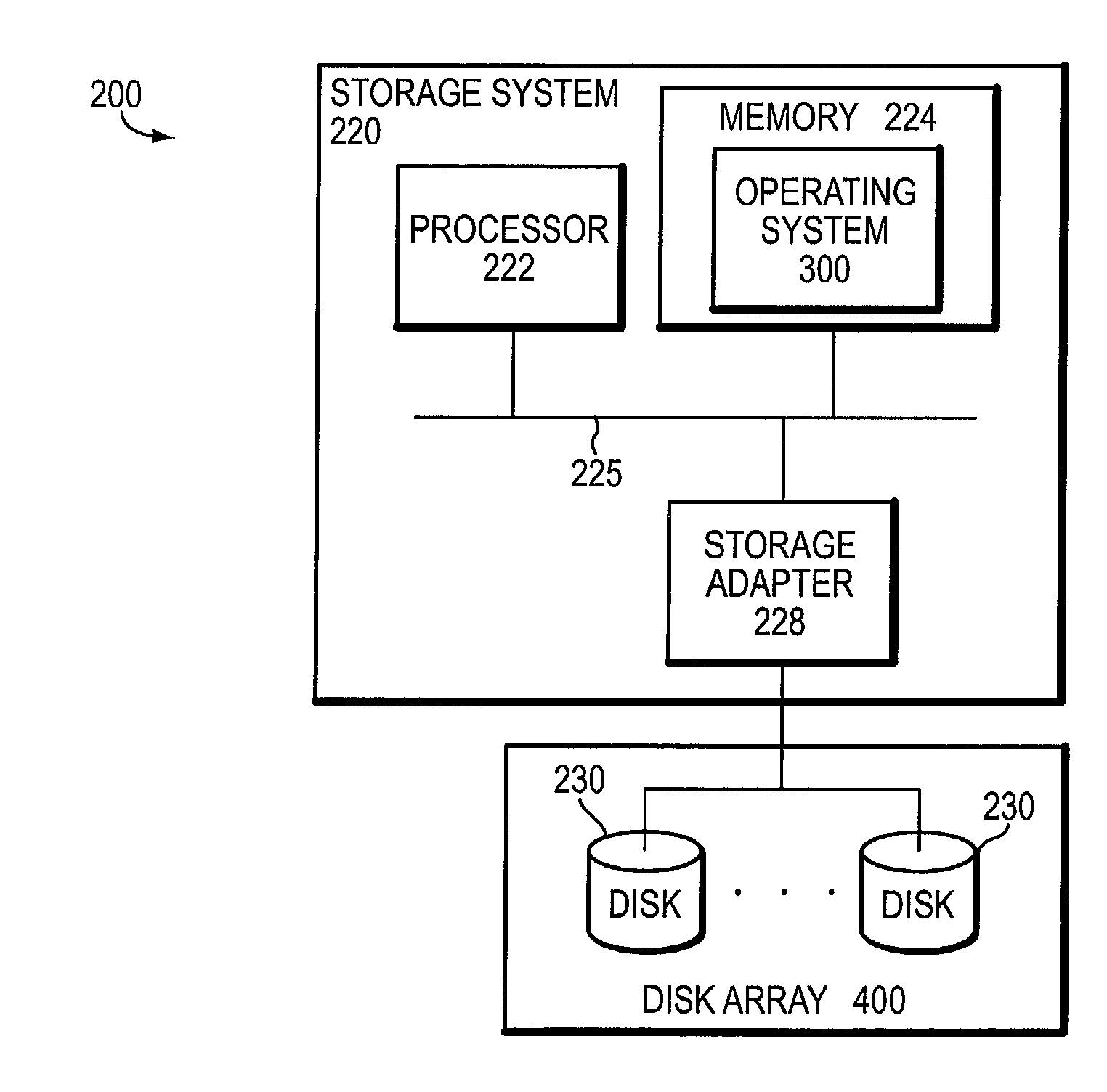
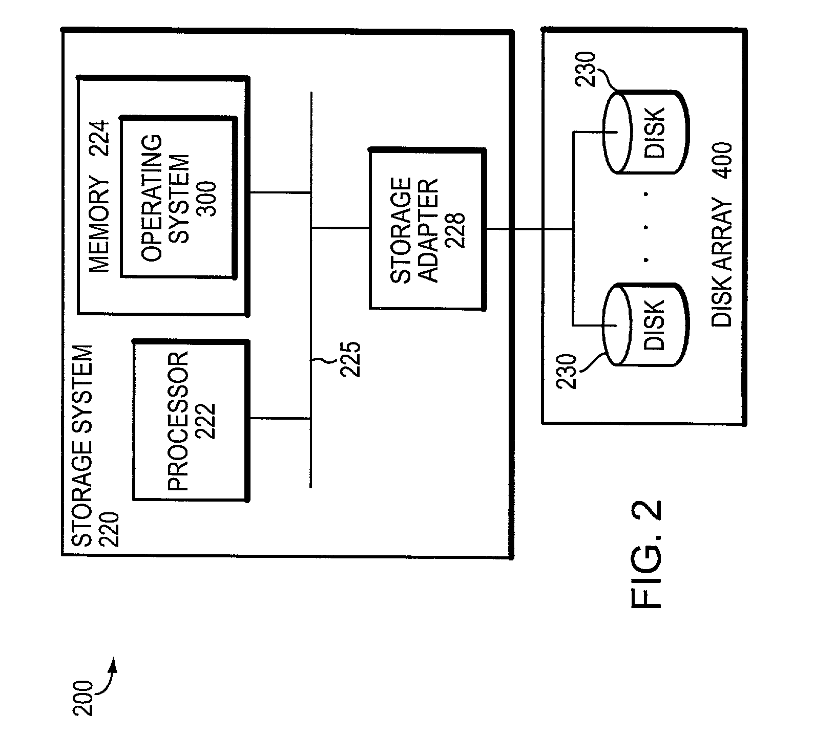
[0036]FIG. 2 is a schematic block diagram of an environment 200 including a storage system 220 that may be advantageously used with the present invention. The inventive technique described herein may apply to any type of special-purpose (e.g., file server or filer) or general-purpose computer, including a standalone computer or portion thereof, embodied as or including a storage system 220. Moreover, the teachings of this invention can be adapted to a variety of storage system architectures including, but not limited to, a network-attached storage environment, a storage area network and a disk assembly directly-attached to a client or host computer. The term “storage system” should therefore be taken broadly to include such arrangements in addition to any subsystems configured to perform a storage function and associated with other equipment or systems.

[0037]In the illustrative embodiment, the storage system 220 comprises a processor 222, a memory 224 and a storage adapter 228 inter...


PUM


Abstract

A “row-diagonal” (R-D) parity technique reduces overhead of computing diagonal parity for a storage array adapted to enable efficient recovery from the concurrent failure of two storage devices in the array. The diagonal parity is computed along diagonal parity sets that collectively span all data disks and a row parity disk of the array. The parity for all of the diagonal parity sets except one is stored on the diagonal parity disk. The R-D parity technique provides a uniform stripe depth and an optimal amount of parity information.

Description

CROSS-REFERENCE TO RELATED APPLICATION[0001]The present invention is related to the following co-pending and commonly assigned U.S. patent application Ser. No. 10 / 035,603 filed on Dec. 28, 2001 titled, Correcting Multiple Block Data Loss in a Storage Array Using a Combination of a Single Diagonal Parity Group and Multiple Row Parity Groups, which was filed on even date herewith and which application is hereby incorporated by reference as though fully set forth herein.FIELD OF THE INVENTION[0002]The present invention relates to arrays of storage systems and, more specifically, to a technique for efficiently reconstructing any one or combination of two failing storage devices of a storage array.BACKGROUND OF THE INVENTION[0003]A storage system typically comprises one or more storage devices into which data may be entered, and from which data may be obtained, as desired. The storage system may be implemented in accordance with a variety of storage architectures including, but not limit...

Claims


Application Information

Patent Timeline
IPC IPC(8): G11C29/00G06F11/00G06F3/06G06F11/10
CPCG06F11/1076
Inventor CORBETT, PETER F.KLEIMAN, STEVEN R.ENGLISH, ROBERT M.
Owner NETWORK APPLIANCE INC
Learn More