
Solid electrolytic capacitor, circuit board having built-in solid electrolytic capacitor and methods for manufacturing them

a solid electrolytic capacitor and solid electrolytic technology, which is applied in the direction of electrolytic capacitors, capacitor electrodes, liquid electrolytic capacitors, etc., can solve the problems of large resistance of insulating oxide films and worse impedance characteristics of capacitors, and achieve the effect of reducing esl

Inactive Publication Date: 2006-01-24
TDK CORPARATION
View PDF13 Cites 33 Cited by
  • Summary
  • Abstract
  • Description
  • Claims
  • Application Information

AI Technical Summary

Benefits of technology

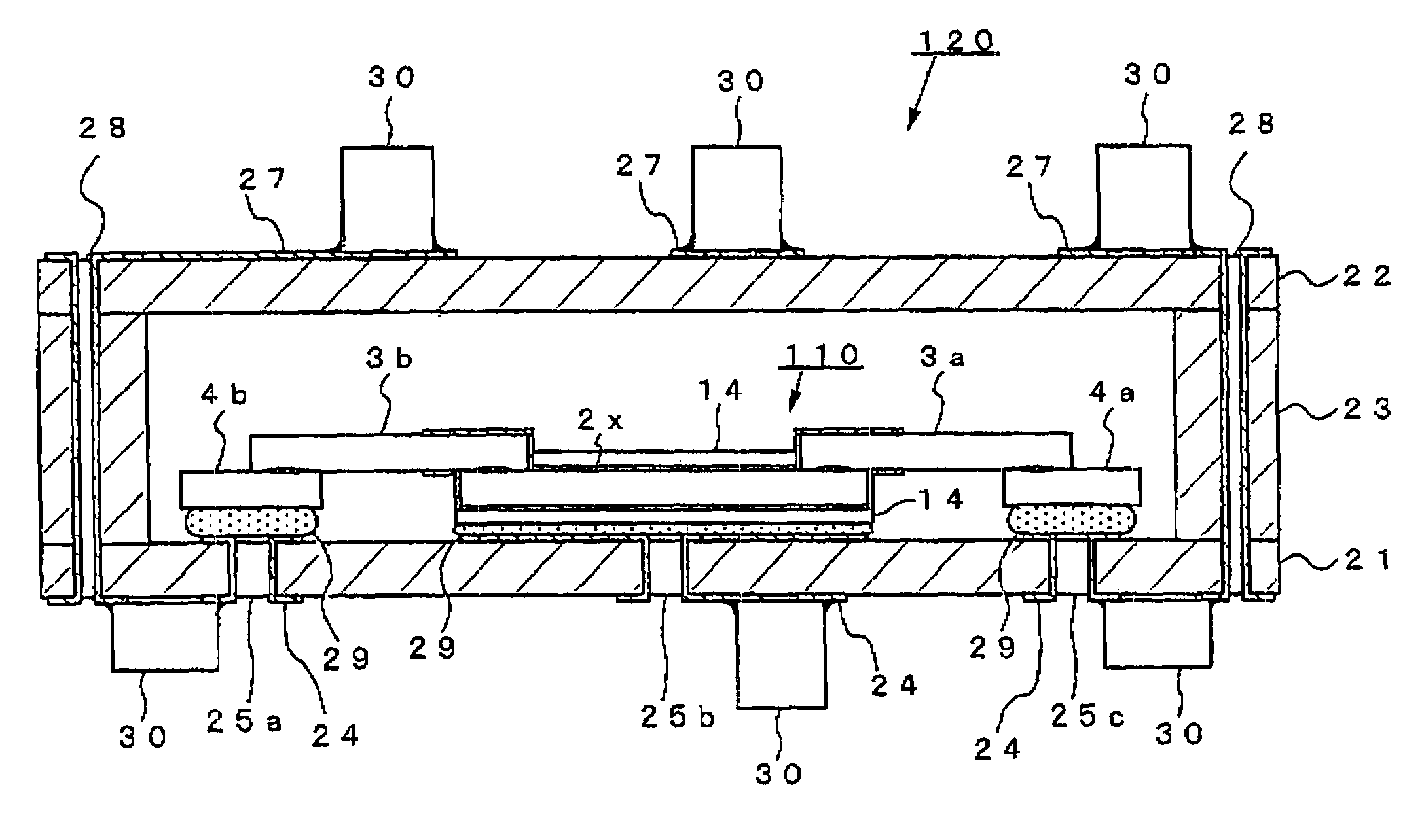
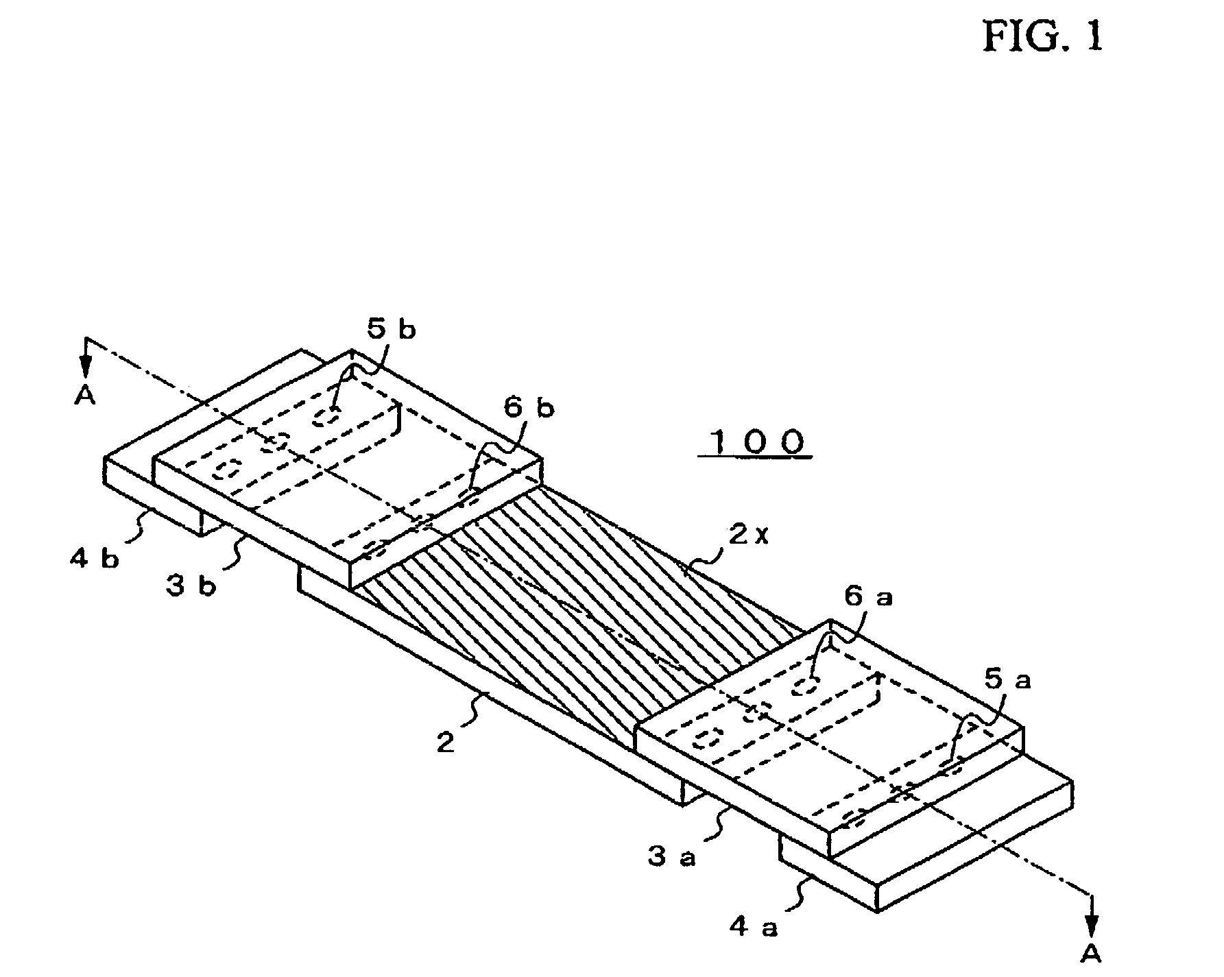
The present invention provides a solid electrolytic capacitor and a circuit board with a built-in solid electrolytic capacitor that can reduce ESL and has a desired impedance characteristic. The invention achieves this by bonding one end portion region of a valve metal body to one of two opposite end portion regions of a foil-like valve metal substrate formed with an insulating oxide film on the surface, thereby establishing electric connection between the valve metals. Even in the case where insulating oxide films are formed on the edge portions of the foil-like valve metal substrate, the resistance of the insulating oxide film can be reduced. The invention also provides a method for manufacturing the solid electrolytic capacitor and the circuit board.

Problems solved by technology

However, it was found that in the case of building a solid electrolytic capacitor including the electrode body for a solid electrolytic capacitor thus obtained by forming the insulating oxide film at the edge portions of the foil-like valve metal substrate in a circuit board, an insulating oxide film formed on the surface of the valve metal body with passage of time and as a result, when contacts with other electronic devices to be mounted on the circuit board were formed on the surface of the valve metal body whose surface was not roughened, the resistance of the insulating oxide film became large and the impedance characteristic of the capacitor became worse.

Method used


Image

  • Solid electrolytic capacitor, circuit board having built-in solid electrolytic capacitor and methods for manufacturing them
  • Solid electrolytic capacitor, circuit board having built-in solid electrolytic capacitor and methods for manufacturing them
  • Solid electrolytic capacitor, circuit board having built-in solid electrolytic capacitor and methods for manufacturing them

Examples


working example 1

[0160]A solid electrolytic capacitor including a solid high molecular polymer electrolyte layer was prepared in the following manner.

[0161]A copper foil cut from a copper foil sheet so as to have a size of 0.5 cm×1 cm and a thickness of 60 μm and an aluminum foil whose surface was not roughened cut from an aluminum foil sheet so as to have a size of 1 cm×1 cm and a thickness of 60 μm were superposed in such a manner that one end portion regions thereof were overlapped by 1 mm and the superposed portions thereof were bonded and electrically connected using a “40 kHz-Ultrasonic Welding Machine” manufactured by Branson Ultrasonics Division of Emerson Japan Limited, thereby forming a connected body of the copper foil and the aluminum foil whose surface was not roughened. Thus, two of the connected bodies were fabricated.

[0162]An aluminum foil was cut from the sheet of an aluminum foil having a thickness of 100 μm which was formed with an aluminum oxide film on the surface thereof and wh...

working example 2

[0183]Similarly to in Working Example 1, three three-terminal type solid electrolytic capacitors were fabricated.

[0184]The three solid electrolytic capacitors were superposed on each other so that one of the anode lead electrodes, the cathode electrode formed with the paste layers (conductive layers) and the other anode lead electrode of the three-terminal type solid electrolytic capacitors were overlapped. The cathode electrodes were integrated with each other using a silver system conductive adhesive agent and the pair of anode lead electrodes were integrated with each other using a “YAG Laser Spot Welding Machine” manufactured by NEC Corporation.

[0185]In this manner, a solid electrolytic capacitor unit including the laminated three three-terminal type solid electrolytic capacitors was fabricated.

[0186]Further, similarly to in Working Example 1, two glass cloth containing epoxy resin insulating substrates were fabricated.

[0187]On the other hand, two substrates each formed of glass...

working example 3

[0208]A discrete-type and three-terminal type solid electrolytic capacitor was fabricated in the following manner.

[0209]An aluminum foil was first cut from an aluminum foil sheet whose surface was roughened and which was formed with an aluminum oxide film on the surface thereof and had a thickness of 100 μm, so as to have a size of 0.7 cm2. Further, two aluminum foils were cut from an aluminum foil sheet whose surface was not roughened and which had a thickness of 60 μm, so that each had the same width as that of the aluminum foil whose surface was roughened and a size of 0.2 cm2.

[0210]Then, one of the aluminum foils whose surfaces were not roughened was superposed on the aluminum foil whose surface was roughened in such a manner that an end portion region thereof and one end portion region of the aluminum foil whose surface was not roughened were overlapped by 0.5 mm. Then, the end portion regions overlapped with each other were bonded and electrically connected using the ultrasoni...


PUM

PropertyMeasurementUnit
electric conductivityaaaaaaaaaa
thicknessaaaaaaaaaa
thicknessaaaaaaaaaa

Abstract

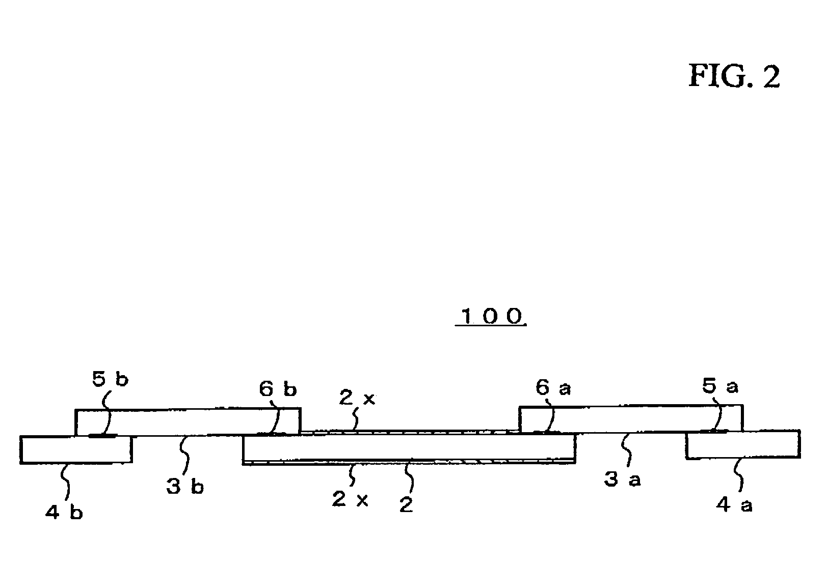
An electrode body 100 of a solid electrolytic capacitor component includes a foil-like aluminum substrate 2 whose surface is roughened or enlarged and which is formed with an aluminum oxide film the surface thereof as an insulating oxide film, two foil-like aluminum substrates 3a,3b whose surfaces are not roughened, and two foil-like copper substrates 4a,4b as a metal electric conductor for constituting a lead electrode. On the whole surface of the foil-like aluminum substrate 2, an anode electrode 14 including a solid high molecular polymer electrolyte layer 11, a graphite paste layer 12 and a silver paste layer 13 is formed. The thus constituted solid electrolytic capacitor component 110 is accommodated in a substantially closed space defined by a first insulating substrate 21 and a second insulating substrate 22, thereby fabricating a three-terminal type solid electrolytic capacitor.

Description

FIELD OF THE INVENTION[0001]The present invention relates to a solid electrolytic capacitor, a circuit board having a built-in solid electrolytic capacitor and methods for manufacturing them and, particularly, to a solid electrolytic capacitor and a circuit board having a built-in solid electrolytic capacitor constituted by forming a solid high molecular polymer electrolyte layer and a conductive layer on a foil-like valve metal substrate formed with an insulating oxide film on the surface thereof and suitable for being mounted on or built in a circuit board, and methods for manufacturing them.DESCRIPTION OF THE PRIOR ART[0002]An electrolytic capacitor is conventionally formed by employing a so-called valve metal capable of forming an insulating oxide film such as aluminum, titanium, brass, nickel, tantalum or the like as an anode, anodizing the surface of the valve metal to form an insulating oxide film thereon, forming an electrolyte layer substantially serving as a cathode, and f...

Claims


Application Information

Patent Timeline
Patent Type & Authority Patents(United States)
IPC IPC(8): H01G9/00H01G2/06H01G9/012H01G9/04H01G9/08H01G9/14
CPCH01G2/065H01G9/012H01G11/48H01G9/14Y10T29/417Y02E60/13
Inventor KOBAYASHI, MASAAKITOGASHI, MASAAKI
Owner TDK CORPARATION
Learn More