Diversity receiver
a receiver and diversity technology, applied in diversity/multi-antenna systems, polarisation/directional diversity, transmission monitoring, etc., can solve the problems of unable to predict the fading fluctuation, conduct antenna switching before the reception signal level drops, and code errors frequently occur in digital transmissions. , to achieve the effect of increasing the accuracy of snr estimation for the received signal
- Summary
- Abstract
- Description
- Claims
- Application Information
AI Technical Summary
Benefits of technology
Problems solved by technology
Method used
Image
Examples
embodiment 1
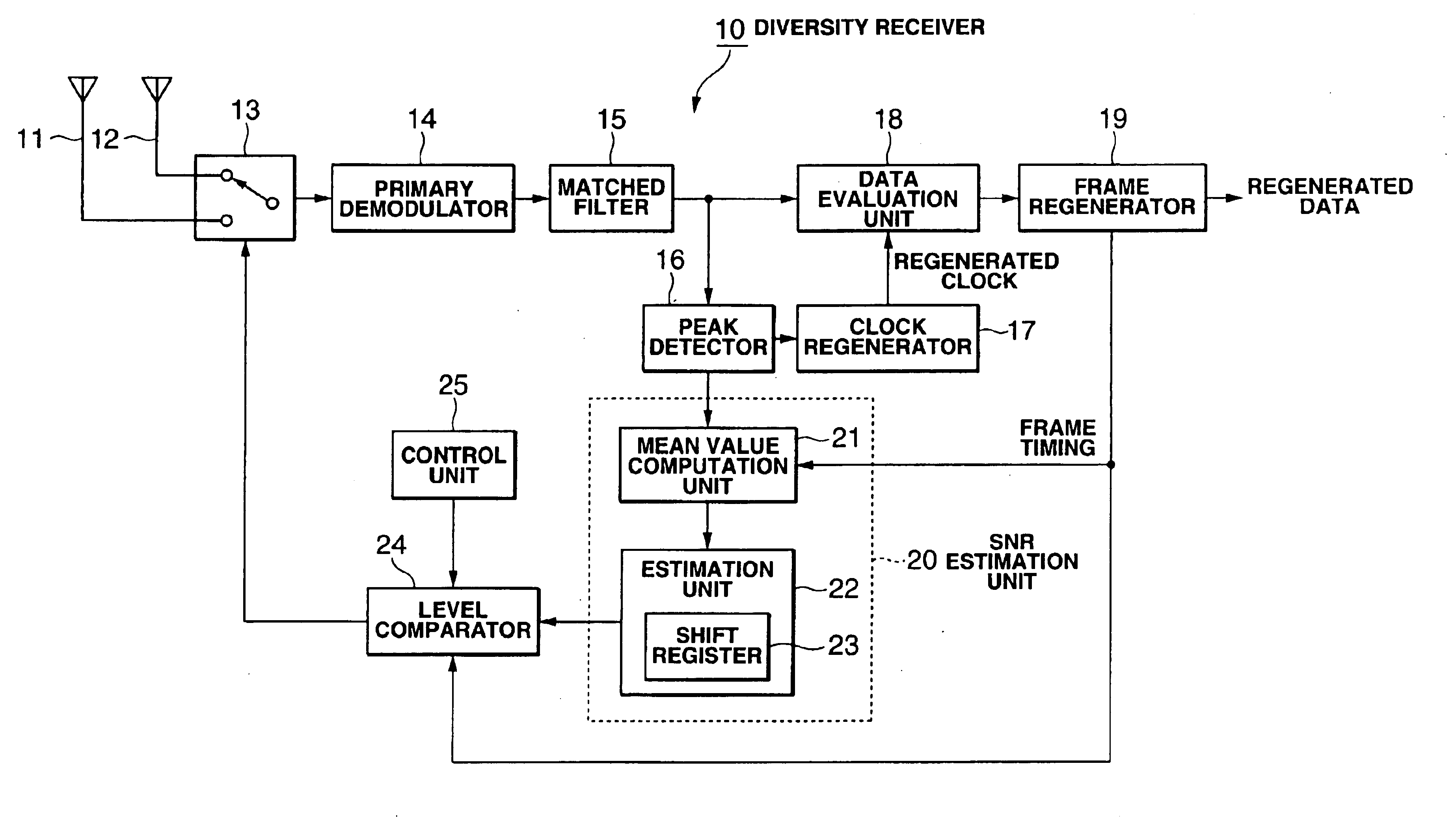
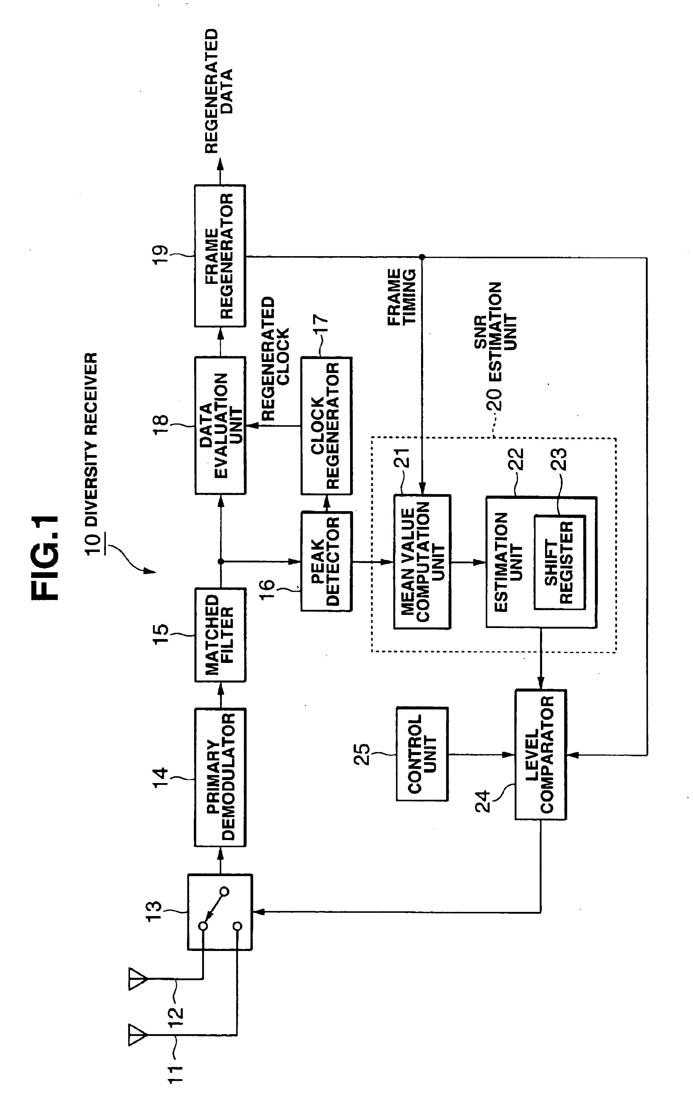
[0015]FIG. 1 is a functional block diagram of the diversity receiver used in the direct spread spectrum communication system. As shown in the figure, a diversity receiver 10 is composed mainly of a plurality of antennas 11, 12, an antenna switch 13, a primary demodulator 14, a matched filter 15, a peak detector 16, a clock regenerator 17, a data evaluation unit 18, a frame separator 19, a SNR estimation unit 20, a level comparator 24, and a control unit 25.
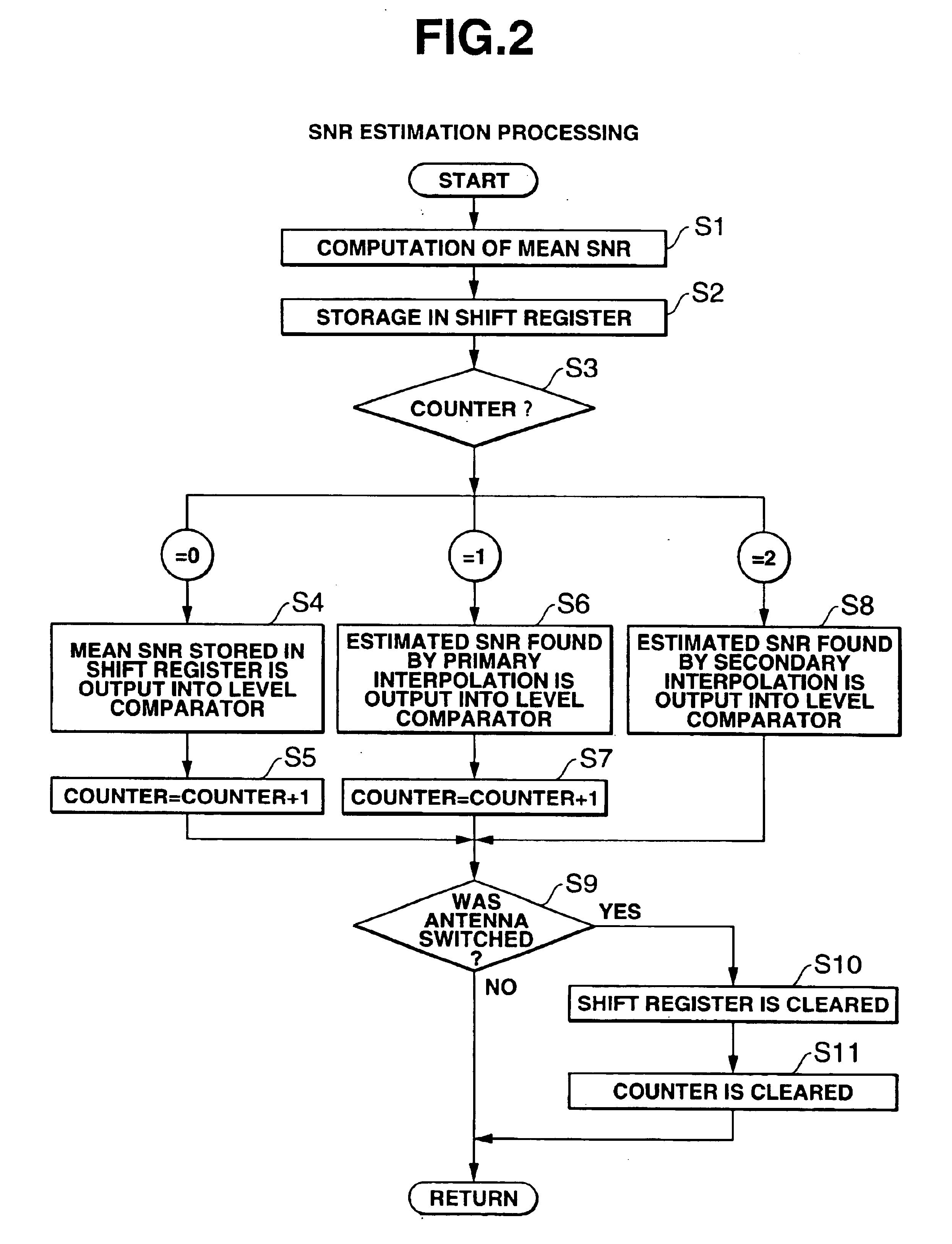
[0016]In direct spread spectrum communication, a spread spectrum signal of a base band is generated by multiplying the data which is to be transmitted by a spread code. At the transmitting side of the spread spectrum communication system, a wireless signal obtained by modulating the propagating wave (carrier) with this base-band spread spectrum signal (chip data) is transmitted. This wireless signal arrives at antennas 11, 12. The primary demodulator 14 demodulates the wireless signal received via the antenna 11 or 12 selected by ...
embodiment 2
[0027]FIG. 3 is a functional block diagram of a diversity receiver in a M-ary / DS system. As shown in the figure, a diversity receiver 30 mainly comprises a plurality of antennas 11, 12, an antenna switch 13, a primary demodulator 14, a total of N matched filters 15-1, 15-2, . . . , 15-N, a peak detector 16, a clock regenerator 17, a data evaluation unit 18, a frame separator 19, a SNR estimation unit 20, a level comparator 24, a control unit 25, and a maximum value detection unit 26.
[0028]The primary demodulator 14 demodulates the wireless signal received via the antenna 11 or 12 selected by the antenna switch 13 and outputs the chip data as a detection output. A total of N matched filters 15-1, 15-2, . . . , 15N arranged in parallel, the number thereof corresponding to the M-ary system series number N, are connected to the last stage of the primary demodulator 14, and chip data is supplied to each matched filter 15-1, 15-2, . . . , 15-N. The maximum value detector 26 selects the ma...
PUM
 Abstract
Description
Claims
Application Information
 - R&D
- Intellectual Property
- Life Sciences
- Materials
- Tech Scout
- Unparalleled Data Quality
- Higher Quality Content
- 60% Fewer Hallucinations
Browse by: Latest US Patents, China's latest patents, Technical Efficacy Thesaurus, Application Domain, Technology Topic, Popular Technical Reports.
© 2025 PatSnap. All rights reserved.Legal|Privacy policy|Modern Slavery Act Transparency Statement|Sitemap|About US| Contact US: help@patsnap.com


