
Method and apparatus for determining a precoding matrix

a precoding matrix and matrix technology, applied in the field of wireless communication systems, can solve the problems of inability to determine the optimal precoding matrix, inability to guarantee the performance enhancement of the wireless communication system by open-loop mimo schemes, and inability to achieve diversity gain in low-mobility communication environments, so as to achieve enhanced diversity gain, reduced number of retransmissions, and enhanced diversity gain

Active Publication Date: 2012-02-23
WIRELESS ALLIANCE LLC
View PDF2 Cites 16 Cited by
  • Summary
  • Abstract
  • Description
  • Claims
  • Application Information

AI Technical Summary

Benefits of technology

[0018]According to the embodiments of the present invention, a diversity gain can be enhanced at a communication environment.
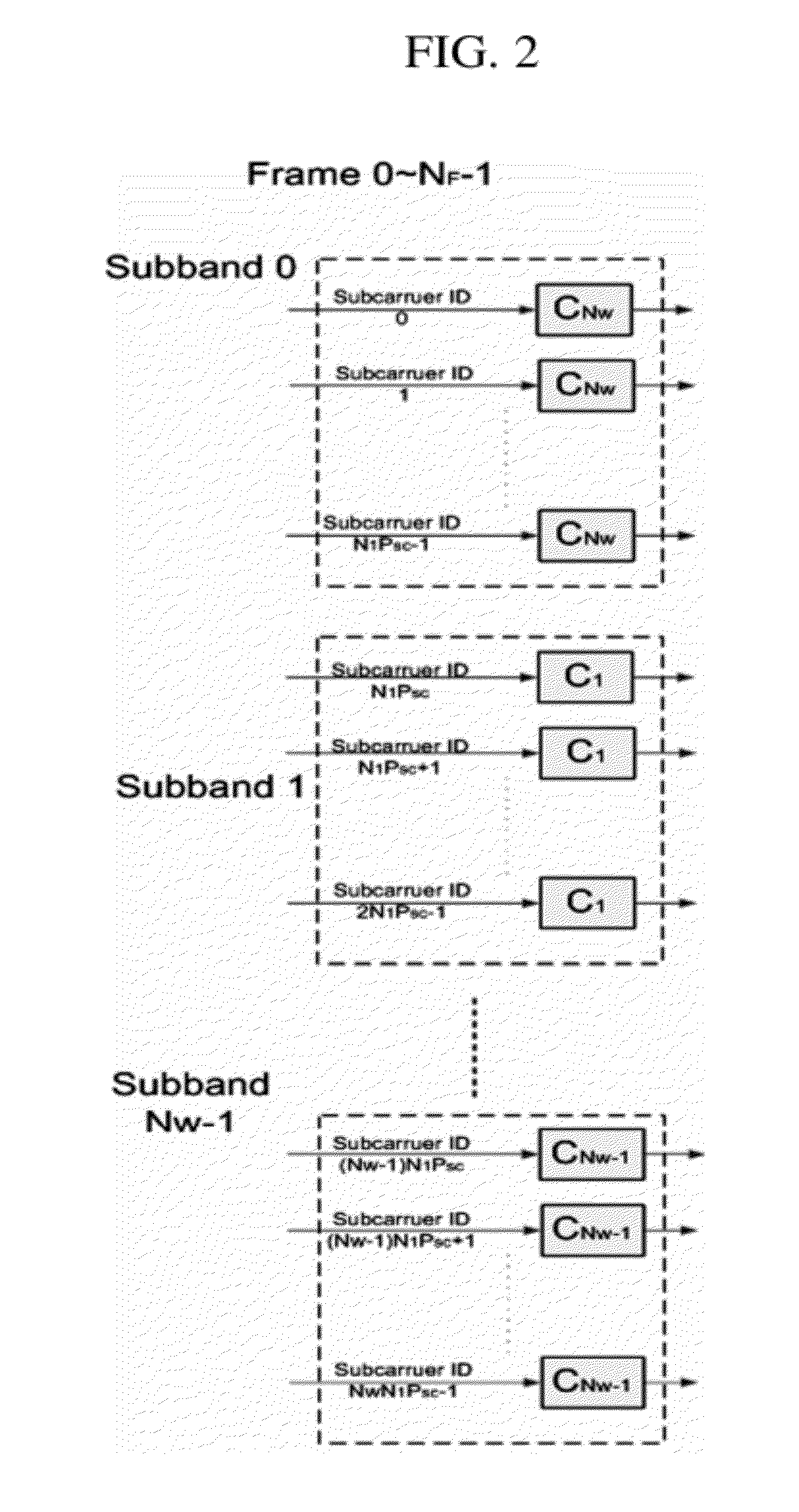
[0019]Moreover, by changing a precoding matrix to be applied to each subcarrier per predetermined frame period, the diversity gain can be enhanced even at the static communication environment or the low-mobility communication environment.
[0020]Furthermore, when retransmitting each stream with the HARQ scheme, by changing a precoding matrix to be applied to a corresponding stream according to the HARQ retransmission period, the number of retransmissions can be reduced, and thus the HARQ gain can be enhanced.

Problems solved by technology

However, since Channel State Information (CSI) is not fed back from a receiving end for selecting a precoding matrix unlike in the closed-loop MIMO scheme, the open-loop MIMO scheme cannot guarantee the performance enhancement of the wireless communication system when determining a precoding matrix according to the above-described method.
Moreover, in the open-loop MIMO scheme, when determining a precoding matrix according to the above-described method, a diversity gain is not obtained at a low-mobility communication environment because the precoding matrix is not changed for entire time, and consequently, the optimal precoding matrix cannot be determined.

Method used


Image

  • Method and apparatus for determining a precoding matrix
  • Method and apparatus for determining a precoding matrix
  • Method and apparatus for determining a precoding matrix

Examples


Embodiment Construction

[0026]Reference will now be made in detail to the exemplary embodiments of the present invention, examples of which are illustrated in the accompanying drawings. Wherever possible, the same reference numbers will be used throughout the drawings to refer to the same or like parts.

[0027]Hereinafter, a method and apparatus for determining precoding matrix method according to embodiments of the present invention will be described in detail with reference to the accompanying drawings.

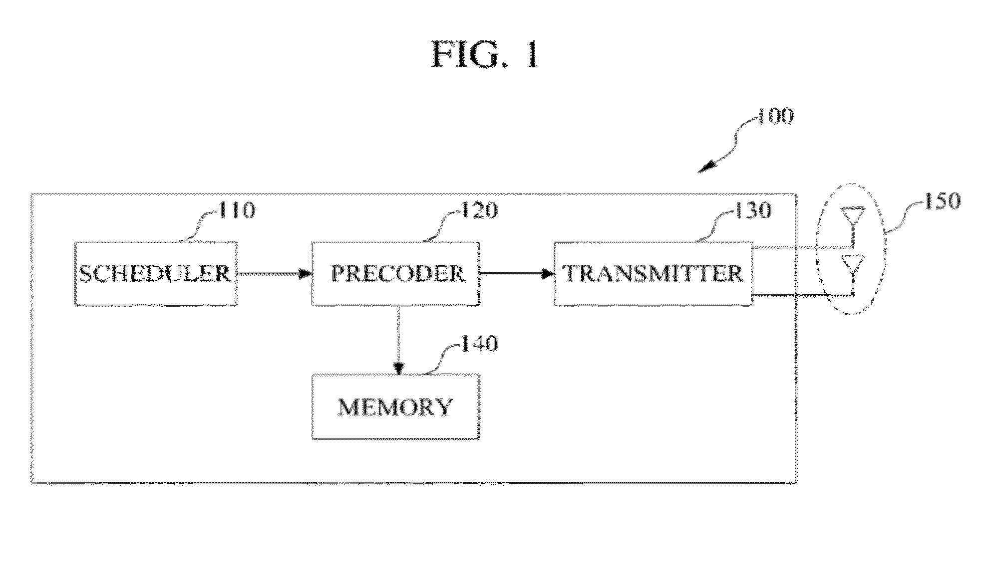
[0028]FIG. 1 is a block diagram schematically illustrating a precoding matrix determining apparatus according to an embodiment of the present invention. A precoding matrix determining apparatus 100 of FIG. 1 may be included in a transmitting end such as a base station. In an embodiment, the transmitting end uses an open-loop MIMO scheme that can determine a precoding matrix without feedback from a receiving end such as a terminal.

[0029]Referring to FIG. 1, the precoding matrix determining apparatus 100 inclu...


PUM


Abstract

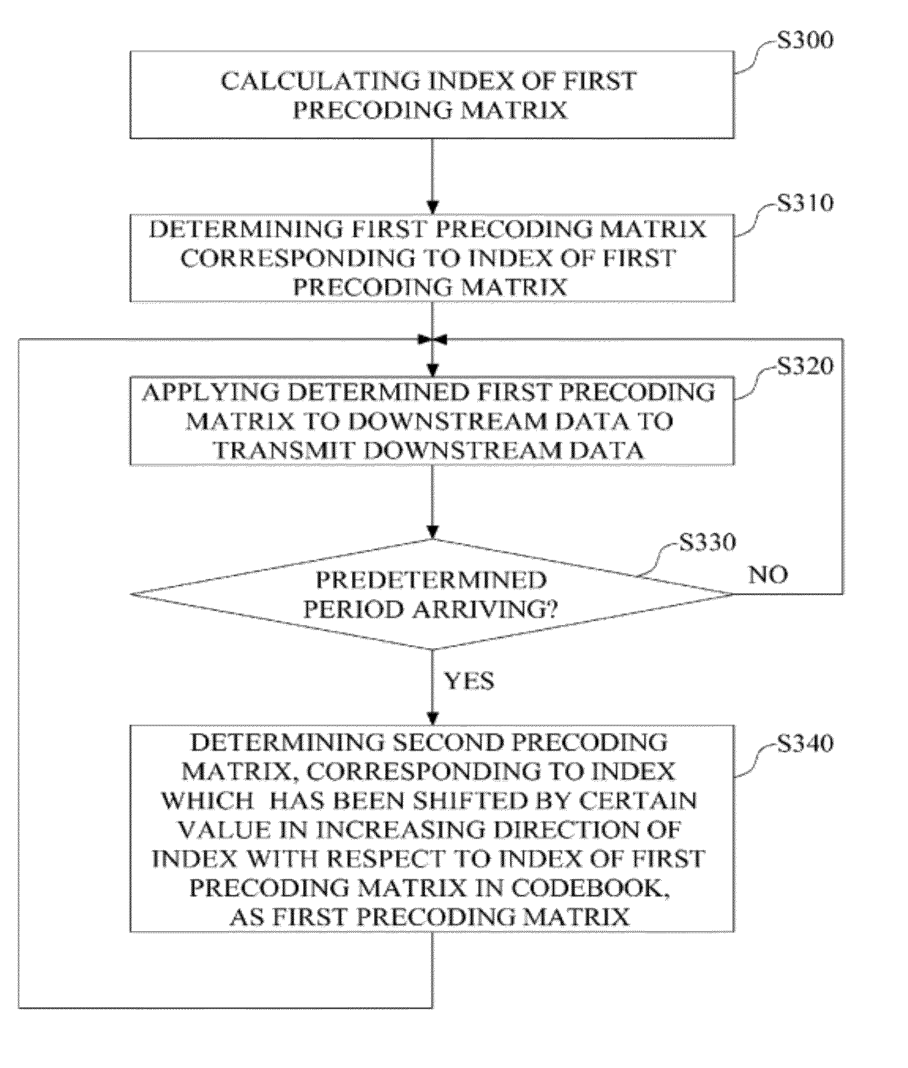
Disclosed is a method for determining precoding matrix based on an open-loop MIMO scheme, which can enhance a diversity gain at a static communication environment or a low-mobility communication environment. The method for determining precoding matrix applies a first precoding matrix to downstream data to transmit the downstream data through a plurality of antennas, the first precoding matrix being selected from a codebook which comprises a plurality of precoding matrixes, and changes the first precoding matrix to a second precoding matrix per predetermined period, and applying the second precoding matrix to the downstream data to transmit the downstream data through the antennas. The second precoding matrix is a precoding matrix corresponding to an index which has been shifted by a certain value from an index of the first precoding matrix in a direction where an index of a precoding matrix increases, in the codebook

Description

TECHNICAL FIELD[0001]The present invention relates to a wireless communication system, and more particularly, to determination of a precoding matrix in a wireless communication system.BACKGROUND ART[0002]The Institute of Electrical and Electronics Engineers (IEEE) 802 Committee is planning to develop technical standard for IEEE 802.16m, being technical standard that has been further advanced by one level than the current standard of mobile WiMAX, as the next generation standard of WiBro / mobile WiMAX. IEEE 802.16m has a transmission rate of 100 Mbps as a target upon moving, and has a transmission rate of 1 Gbps as a target upon fixing.[0003]The wireless communication system based on IEEE 802.16m is using the Multi-Input Multi-Out (MIMO) scheme where a transmitting end including a plurality of antennas transmits different data through the respective antennas, for the enhancement in efficiency of data transmission. With the use of the MIMO scheme, a wireless communication system obtain...

Claims


Application Information

Patent Timeline
Patent Type & Authority Applications(United States)
IPC IPC(8): H04L25/497
CPCH04B7/0413H04L2025/03764H04L25/03942H04B7/0639H04B7/0456H04L1/1812
Inventor LI, JIANJUNAHN, JAE HYEONLI, ZHENGZIJEON, HYUNG JOON
Owner WIRELESS ALLIANCE LLC
Learn More