
Threaded pipe with surface treatment

a surface treatment and threaded pipe technology, applied in the field of threaded pipes, can solve the problems of excessive dope not being evacuated through the end of the threaded portions of the pipe segments, affecting the corrosion resistance of the pipe, and galling in the threads and other surfaces of the pipe in sliding contact, etc., to achieve excellent make-up properties and corrosion resistance.

Inactive Publication Date: 2005-12-06
TENARIS CONNECTIONS
View PDF15 Cites 72 Cited by
  • Summary
  • Abstract
  • Description
  • Claims
  • Application Information

AI Technical Summary

Benefits of technology

[0013]The main object of this invention is to eliminate the above mentioned drawbacks by means of a threaded pipe segment of definite length having a threaded portion, adapted to form threaded joints for pipes, with excellent make up properties and corrosion resistance within the widest range of environmental and operational conditions common nowadays, assuring optimum performance even after several assembling and disassembling operations of the joint composed of pipe segments according to the present invention.
[0027]By using dry lubricant coatings and dry corrosion inhibitor layers on a threading formed by the connection of tube segments, it is possible to transport and store the pipes in the oilfield without risking that the pipes lose their integrity because of corrosion on the threaded portions forming the connections. The connections composed by pipes treated with the method according to the invention have the further advantage that they can be assembled in the oilfield without removing the corrosion protection layer and without the addition of oil or grease.

Problems solved by technology

During assembling operation a major problem is the occurrence of galling in threads and other surfaces of the pipes in sliding contact.
In addition to the aforementioned risks, the use of dope entails other operations, i.e. cleaning and doping of the connectors that have to be carried out in the oilfield in often adverse environmental conditions.
These undesirable extra tasks are expensive and time consuming.
Another potential risk in the use of dope is the danger of the so-called “overdoping”, i.e. the concrete possibility of laying too much dope on the threads of the connectors which has the consequence that, during make up of the connector, the excess of dope cannot be evacuated through the end of the threaded portions of the pipe segments.
The trapped dope can thus develop high pressure within the connector, and under circumstances such pressure is able to produce plastic deformation of the pipe segments in the threaded portion and even the collapse of the male member of the joint.
Once this fact occurs, the connector is no longer effective and the pipe segments and / or the sleeve must be replaced.
Nevertheless, such known solutions do not solve the problems of both assuring high galling resistance during make up operation in the oil field and high corrosion resistance by using dry coatings on the threaded portion of the pipes, this latter feature being necessary for the transport and storage of the pipes in such a way that they are not damaged.
However, in both documents, no corrosion protection is provided by the disclosed solutions.
Similarly, the U.S. Pat. No. 4,692,988 does not disclose a method of corrosion protection; additionally, it provides for the use of oil to perform the assembly of the connection, therefore it is not a dry process and also envisages the unwanted extra work of adding oil.
However, such layer is applied over the dry lubricant coating, and it is necessary to remove it before assembling the connection in the oilfield, which introduces unwanted extra operation.

Method used


Image

  • Threaded pipe with surface treatment
  • Threaded pipe with surface treatment
  • Threaded pipe with surface treatment

Examples


Embodiment Construction

[0036]With reference to the mentioned figures, a pipe according to the present invention will be now described by way of non-limiting example.

[0037]The connection comprises a tube acting as a male component 1, the so-called “pin”, provided with an external frusto-conical surface with threading in the end portion, and a female component 2, the so-called “box”, provided with an internal corresponding frusto-conical threaded surface provided in the end portion of the box, which generally corresponds to a pipe or a connection sleeve. The male component 1 has external threads 3 and the female component 2 has internal threads 4. The enlargement of the threaded portion 5 of the pipe 1 is shown in FIG. 2, where there is provided a protective layer 6 on the surface of the thread. The threaded portion of the female component 2 can have a perfectly similar shape or it can be made without the protective layer and be connected to a male component provided with the protective layer.

[0038]A magnif...


PUM

PropertyMeasurementUnit
Raaaaaaaaaaa
Raaaaaaaaaaa
thicknessaaaaaaaaaa

Abstract

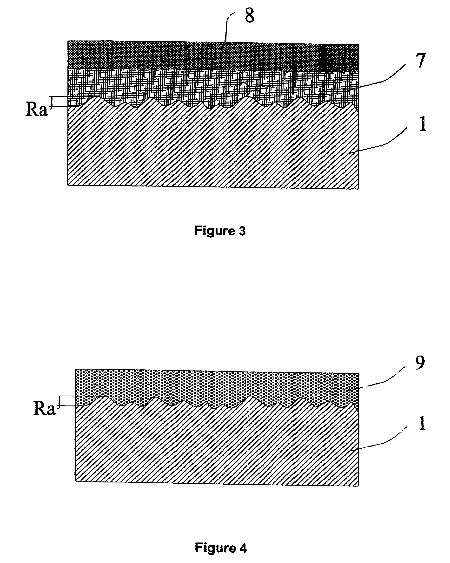
A threaded metallic pipe for oil extraction industry has a threaded end portion with treated surface in which the metal surface has a roughness (Ra) comprised of 2.0 μm and 6.0 μm, which is covered by a uniform layer (7) of a dry corrosion inhibiting coating and a second uniform layer (8) of dry lubricant coating. Alternatively the layers (8, 9) combined into one uniform layer (9) of a dry corrosion inhibiting coating containing a dispersion of particles of solid lubricant.

Description

BACKGROUND OF THE INVENTION[0001]1. Field of Invention[0002]The present invention relates to a threaded pipe, particularly adapted for forming a threaded joint to join pipe segments into strings used in the oil and gas extraction industry, provided with a surface protection of the threaded portion to increase its corrosion and galling resistance properties. Moreover, the present invention relates to a process for making the dry surface protection of the threaded pipe to increase corrosion and galling resistance thereof.[0003]2. Brief Description of the Prior Art[0004]In the oil fields it is common practice to use metallic pipes of a predefined length, joined to form such a string to reach the depth in which there are oil or gas reservoirs or pools for their extraction.[0005]This extraction technique requires to gradually case the well internally, during its boring, which is performed with metallic tubes, the so-called casing of the well. Once the desired depth is reached, there is p...

Claims


Application Information

Patent Timeline
Patent Type & Authority Patents(United States)
IPC IPC(8): F16L15/00F16L58/18
CPCE21B17/042F16L15/001F16L58/182C10M103/04C10M103/06C10N2230/06C10N2250/121C10N2250/14C10N2280/00C10N2030/06C10N2050/023C10N2050/02C10N2080/00
Inventor DELL'ERBA, DIEGOCARCAGNO, GABRIEL E.
Owner TENARIS CONNECTIONS
Learn More