
Method of making single layer capacitor

a single-layer capacitor and capacitor technology, applied in the direction of fixed capacitors, stacked capacitors, fixed capacitor details, etc., can solve the problems of low structural strength of capacitors, undesirable fracturing or chipping, and the quality of devices realizing maximum capacitance is starting to limit the usefulness of certain applications, etc., to achieve high capacitance, easy and inexpensive manufacturing, and good structural strength

Inactive Publication Date: 2005-11-29
PRESIDIO COMPONENTS
View PDF18 Cites 17 Cited by
  • Summary
  • Abstract
  • Description
  • Claims
  • Application Information

AI Technical Summary

Benefits of technology

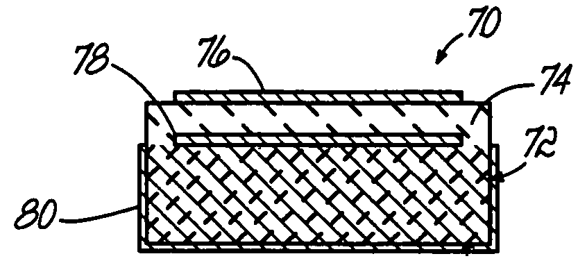
"The present invention provides a way to make a strong and easily manufacturable single-layer capacitor using thin layers. The capacitor can be used on a circuit board and has a high capacitance. The method involves laminating sheets of ceramic material together, dicing them, and firing them to sinter them. The composite material can be made conductive for mounting the capacitor or for plating it with metal. The capacitor has a vertically-oriented dielectric between composite blocks or a horizontally-oriented dielectric on a composite block that can be wire bonded to the circuit board. The method allows for a thin dielectric while maintaining high structural integrity and simplifies the manufacturing process. The green-state method allows for flexibility in capacitor values."

Problems solved by technology

While the form factor of these simple devices—used in quantities of hundreds of millions per year—is highly desirable, the amount of capacitance that can be achieved and quality of the devices realizing maximum capacitance is starting to limit their usefulness in certain applications.
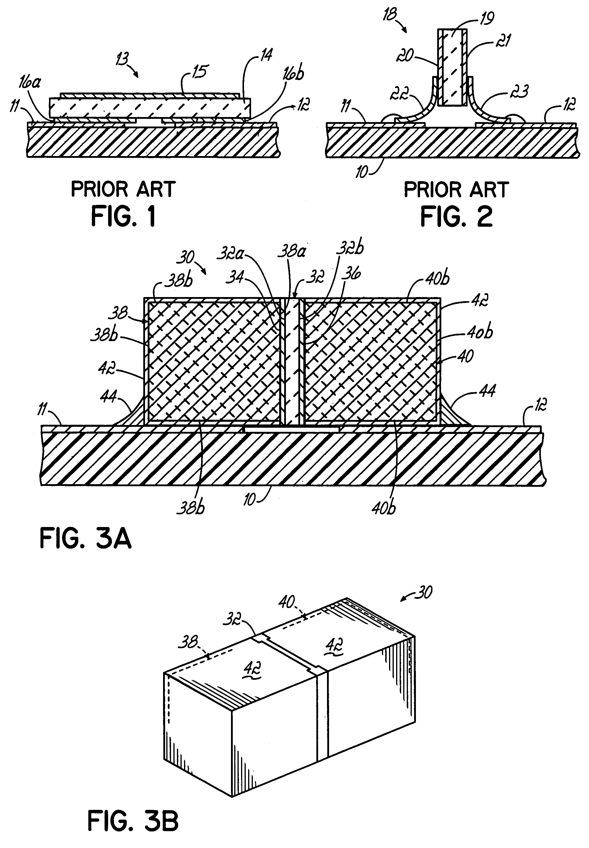
This five mils thickness—necessitated in order to establish some structural strength for the given area size of, for example, 20 mils×20 mils—means that the capacitor does not have much structural strength, and is subject to undesirable fracturing or chipping during routine handling and assembly into circuits.
Thus, the physical resistance to damage of the highest-capacitance “parallel plate” or “single layer” ceramic capacitors is innately poor.
In addition to the difficulties in achieving high capacitance while maintaining structural strength, due to the small size of the capacitors, they are difficult to attach automatically to a pc board.
However, these devices can create unwanted resonances at frequencies above a few gigahertz.
In addition, these capacitors are quite small, typically about 20–25 mils.
At these sizes, the capacitors are difficult to handle, and must be installed using a microscope.
Thus, mounting of the capacitor is difficult and expensive.
Also, the additional requirement of attaching metal leads may further contribute to prohibitive manufacturing costs.
Thus, the capacitors 18 have to be installed manually under a microscope, and robotized or automated circuit fabrication is difficult or impossible to obtain.
While the standing axial-leaded surface mount capacitor described in that patent is an improvement over the prior devices, the end blocks, which are described as 20–25 mils square blocks, must be manually assembled with the dielectric chip, which is a slow, intricate and expensive process subject to inaccurate alignment of the various components and to joint disattachment between the components during shipping and handling.
The smaller the chip size, the more difficult and expensive it will be to mechanically assemble the end blocks to the dielectric chip.
Moreover, in practice, only a limited range of capacitance values may be produced, thereby limiting the flexibility of the product to meet consumer demands.

Method used


Image

  • Method of making single layer capacitor
  • Method of making single layer capacitor
  • Method of making single layer capacitor

Examples


Embodiment Construction

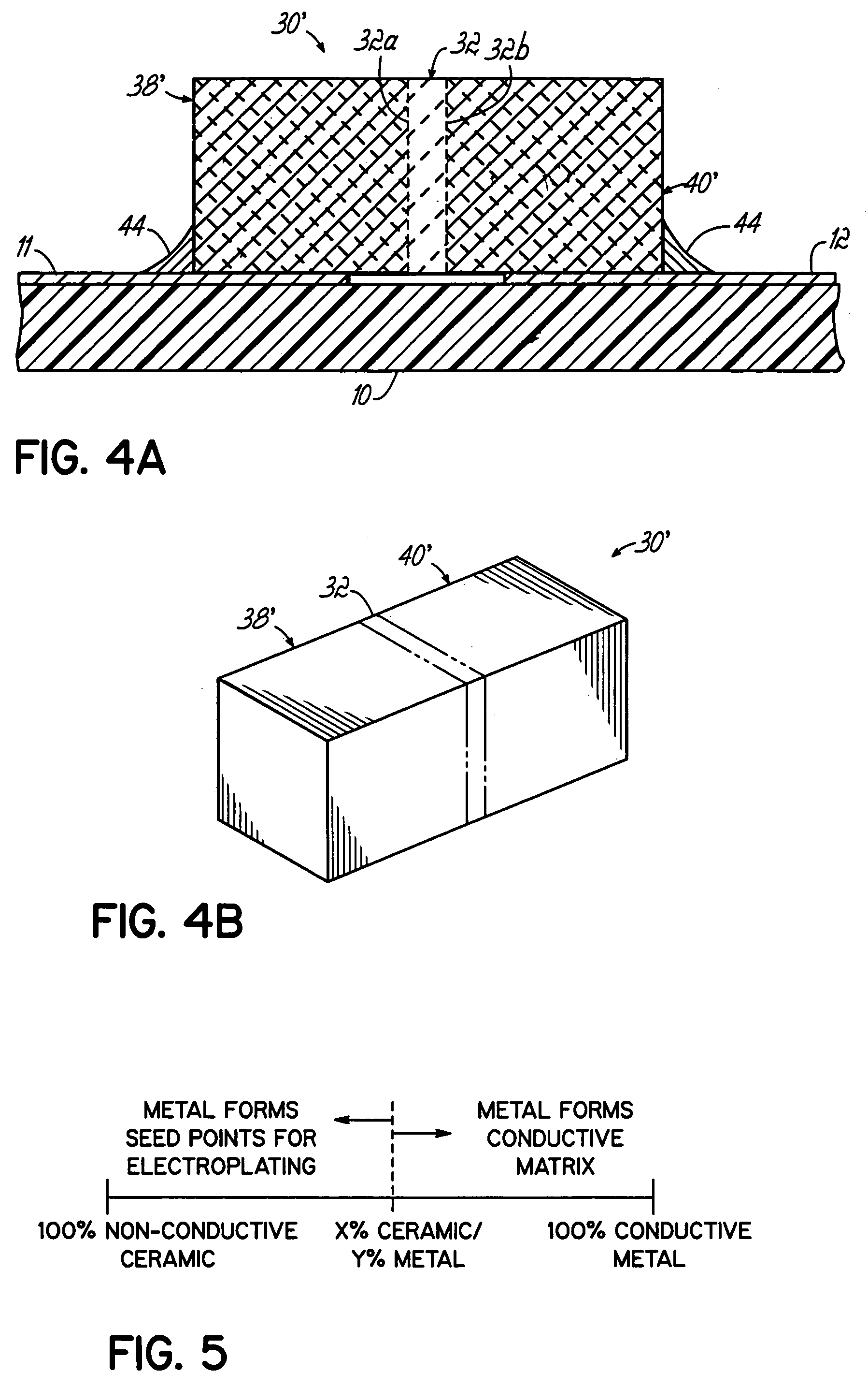
[0031]The present invention provides surface mountable single layer capacitors that may be easily assembled and inexpensively manufactured. The capacitors of the present invention may utilize thin dielectric layers to provide high capacitance without sacrificing structural strength. Structural strength is provided by composite end blocks that are either conductive or plated with conductive metal, which further serve as the electrodes or to electrically connect internal electrodes, or metallizations, of the capacitor to the metal surface traces on the pc board.

[0032]The capacitors of the present invention are manufactured starting in the green state. In one embodiment, a green-state ceramic dielectric sheet is metallized on both sides and placed between a pair of green-state composite metal / ceramic sheets. The sheets are laminated together, then the laminate is diced into a plurality of individual chips. The chips are then fired to sinter the ceramic material. The metallizations on t...


PUM

PropertyMeasurementUnit
thickaaaaaaaaaa
sizesaaaaaaaaaa
capacitanceaaaaaaaaaa

Abstract

A method of making a monolithic or essentially monolithic single layer capacitor with high structural strength and capacitance. Sheets of green-state ceramic dielectric material and ceramic / metal composite material are laminated together, diced into individual chips, and fired to sinter the ceramic together. The composite material may contain an amount of metal sufficient to render the composite conductive whereby the composite may be used for one or both electrodes and for mounting the capacitor to the pc board. Alternatively, the composite material may contain an amount of metal insufficient to render the composite conductive but sufficient to act as seed points for an electroplating process wherein the composite is preferentially coated with conductive metal, and the coated composite is mounted to the pc board and the coating provides an electrical connection to an internal electrode. Vertically-oriented surface mountable capacitors and hybrid capacitors are provided.

Description

CROSS REFERENCE TO RELATED APPLICATION[0001]This application is a divisional of U.S. patent application Ser. No. 10 / 694,125 filed Oct. 27, 2003 now Pat. No. 6,822,847 and entitled SINGLE LAYER CAPACITOR, which is a continuation of U.S. patent application Ser. No. 10 / 188,696 filed Jul. 2, 2002, now U.S. Pat. No. 6,661,639 issued Dec. 9, 2003 and entitled SINGLE LAYER CAPACITOR, the disclosure of which is incorporated herein by reference in its entirety as if completely set forth herein below.FIELD OF THE INVENTION[0002]This invention relates to single layer capacitors, and in particular, surface mountable single layer capacitors and a method of making the capacitors.BACKGROUND OF THE INVENTION[0003]The “parallel plate” or “single layer” ceramic capacitor has a very useful form factor for assembly into microwave frequency and similar electrical circuits. These circuits may be laid out on printed circuit (pc) boards, or be present on integrated circuits (ICs) within chip carriers and o...

Claims


Application Information

Patent Timeline
Patent Type & Authority Patents(United States)
IPC IPC(8): H01G4/005H01G4/06H01G4/12H01G4/228H01G4/33H01L21/02H10B12/00
CPCH01G4/005H01G4/06H01G4/228H01G4/33Y02E60/13
Inventor DEVOE, ALANDEVOE, LAMBERTTRINH, HUNG
Owner PRESIDIO COMPONENTS
Learn More