Ozone generator

Inactive Publication Date: 2005-11-22
HYDRO ELEKTRIK
View PDF9 Cites 0 Cited by
  • Summary
  • Abstract
  • Description
  • Claims
  • Application Information

AI Technical Summary

Benefits of technology

[0005]The object of the present invention is to provide a more effective design for an ozone generator of the aforementioned type, in particular with respect to the capacity.
[0008]The invention is directed to an ozone generator comprising a plurality of plate-like ozone generating elements, stacked one on top of the other, which are in at least partial contact with process water, that is, water enriched with ozone, each of the ozone generating elements having at least one plate-like, electrically insulated inner electrode and at least one likewise plate-like counterelectrode, between which a space is provided for a gas discharge. The essence of the invention lies in the fact that the ozone generating elements are situated at a distance from one another, perpendicular to their plate-like extension, in such a way that the process water is able to flow between the ozone generating elements over substantial surface regions of the plate-like ozone generating elements. This procedure is based on the knowledge that, in order to provide an ozone generator having a higher capacity with at least the same reliability, the ozone generator must be provided with significantly more effective cooling. By distancing the ozone generating elements from one another, the cooling surface is increased considerably in comparison to the known principle according to German Patent 32 47 373 C2. In this manner the individual ozone generating elements may be operated at significantly higher capacities without overheating, thereby enabling correspondingly more effective ozone generation.
[0010]It is also particularly advantageous when the process water is in direct contact with at least one outer electrode of the ozone generating element. In other words, there is no intermediate insulation layer, in particular between the outer electrode and the process water. The effectiveness of the cooling is further increased by use of this measure.
[0011]In a particularly preferred embodiment of the invention, conducting means are provided through which a portion of the process water stream is forced to flow between the ozone generating elements. This procedure further improves the effectiveness of the cooling and thus the capacity of the generator, that is, the maximum possible ozone generation rate. To further improve the cooling, it is also proposed that the conducting means be designed in such a way that the process water flows in a spiral through the intermediate spaces between the ozone generating elements.
[0015]A significant portion of the electrode surfaces may be effectively cooled by this procedure. Thus, it is possible to achieve high ozone generation rates using a comparatively small space. In addition, the number of stacked ozone generating elements is basically unlimited since, with respect to the maximum possible heat removal for a number of ozone generating elements used up to that point, the cooling of the ozone generating elements is far from reaching its capacity limit.
[0016]In a further preferred embodiment of the invention, at least the outer surfaces of the ozone generating elements are made of stainless steel. The outer electrodes are advantageously produced entirely from stainless steel. As the result of the cooling principle for the ozone generating elements via their intermediate spaces, materials may be used which have a considerably lower heat conductivity compared to aluminum, but which have other advantages in contrast to aluminum. The use of stainless steel results in an exceedingly corrosion-resistant design which in turn ensures a comparatively long service life and reliability of the ozone generator.

Problems solved by technology

However, it is this very use of aluminum which causes the heat removal in the aluminum electrodes to be the limiting factor in the design of the allowable maximum capacity.

Method used


Image

  • Ozone generator
  • Ozone generator
  • Ozone generator

Examples


Embodiment Construction

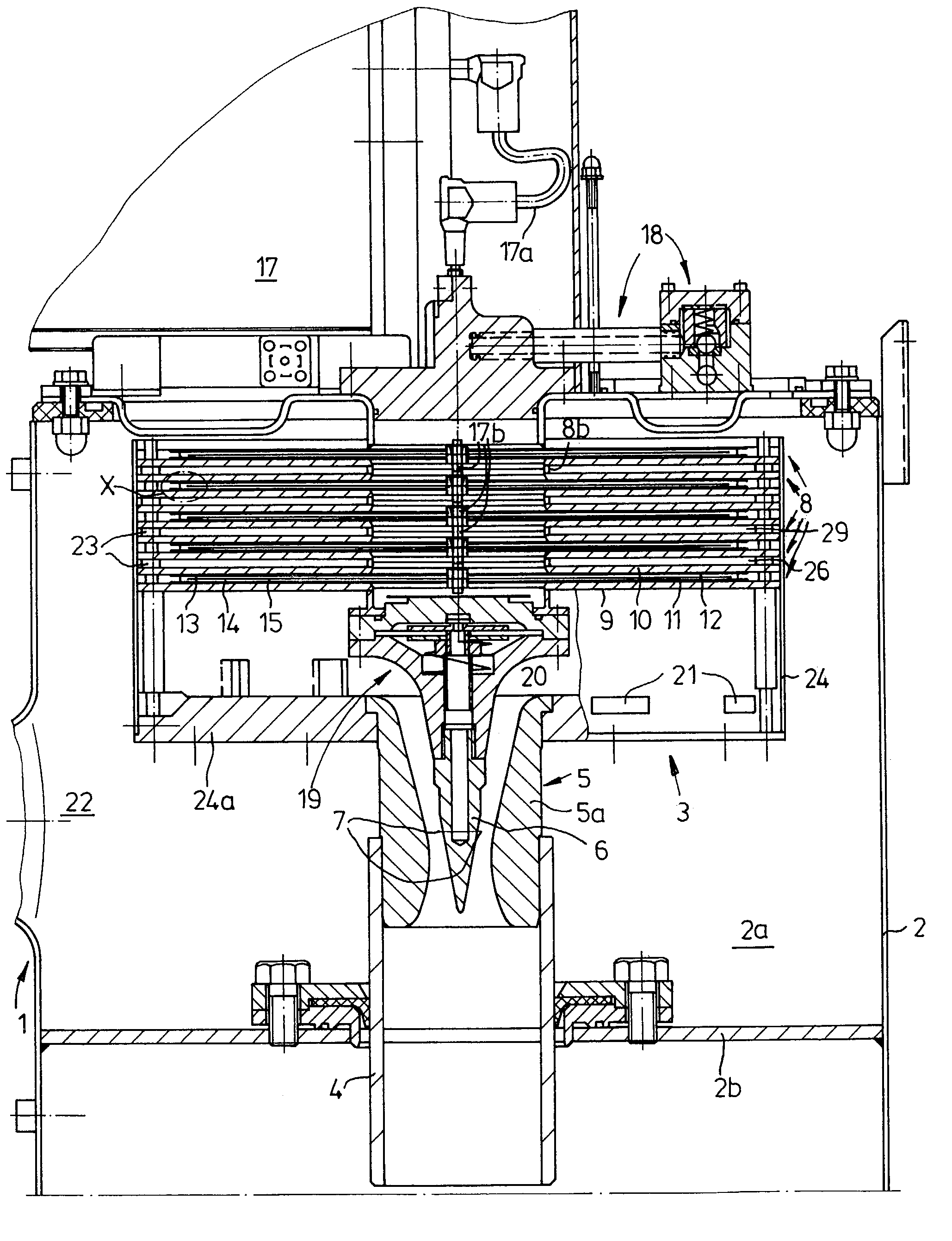
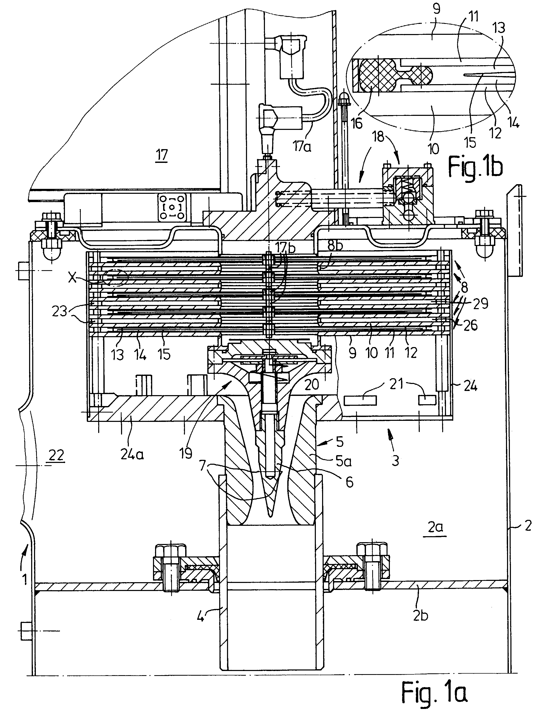
[0023]FIGS. 1a and 1b show an ozone oxidizer 1 having a process chamber housing 2 which is sealed with respect to the outside. An ozone generating unit 3 is situated in process chamber 2a of housing 2. A water feed pipe 4 is sealingly inserted in base 2b of housing 2. Water feed pipe 4 merges into a Venturi nozzle unit 5 mounted on the underside of ozone generating unit 3. Venturi nozzle unit 5 comprises a Venturi nozzle 5a, inside of which an injector element 6 having discharge outlets 7 is centrally situated. Injector element 6 is attached at separate locations to the underside of a stack of ozone generating elements 8 of ozone generating unit 3 by a valve arrangement 19. Water flowing in through water feed pipe 4 is led at high velocity past discharge outlets 7, from which gas having a specified proportion of ozone which has been formed in ozone generating elements 8 flows out.

[0024]Ozone generating elements 8 comprise two outer electrodes 9, 10 (see in particular FIG. 1b), along...


PUM


Abstract

An ozone generator is proposed which comprises a plurality of plate-like ozone generating elements, stacked one on top of the other, which are in at least partial contact with a process water stream, each of the ozone generating elements having at least one plate-like, electrically insulated inner electrode and at least one likewise plate-like counterelectrode, between which a space is provided for a gas discharge. According to the invention, the ozone generating elements are situated at a distance from one another, perpendicular to their plate-like extension, in such a way that process water is able to flow between the ozone generating elements over substantial surface regions of the plate-like ozone generating elements.

Description

FIELD OF INVENTION[0001]The invention relates to an ozone generator comprising a plurality of plate-like ozone generating elements, stacked one on top of the other, which are in at least partial contact with a process water stream, each of the ozone generating elements having at least one plate-like, electrically insulated inner electrode and at least one likewise plate-like counterelectrode, between which a space is provided for a gas discharge.BACKGROUND OF THE INVENTION[0002]An ozone generator having cylindrical plate electrodes in a stacked configuration is known from German Patent 32 47 373 C2, in which two insulating plates are situated between two solid outer electrodes separated at a distance from one another, and an inner electrode is situated between the two insulating plates, forming two discharge chambers. The inner electrode has an outer diameter which is smaller than the diameter of the insulating plates, between which an annular ring running in the vicinity of their e...

Claims


Application Information

Patent Timeline
IPC IPC(8): C01B13/11
CPCC01B13/11C01B2201/12C01B2201/34C01B2201/60C01B2201/76
Inventor BACHHOFER, BRUNO
Owner HYDRO ELEKTRIK
Why Eureka
Try Eureka