
MIMO antenna device, antenna and antenna package

Active Publication Date: 2013-12-05
NAT SUN YAT SEN UNIV
View PDF2 Cites 1 Cited by
  • Summary
  • Abstract
  • Description
  • Claims
  • Application Information

AI Technical Summary

Benefits of technology

The patent is about a MIMO antenna device that doesn't require isolation devices because it creates weak current on the other antenna unit. This creates excellent isolation.

Problems solved by technology

As the demanded wireless transmission data rates continue to grow in the latest wireless communication technologies, such as Long-term evolution (LTE) and WiMAX, the conventional single-input and single-output (SISO) antenna technology is not a preferred choice to the users due to the limited channel capacity.
However, the MIMO antenna technology still has some drawbacks.
M349047 is criticized for inconvenient integration of the antenna and the IC modules.
In the antenna technologies disclosed in U.S. Pat. Nos. 6,239,752, 6,373,447, 6818985 and 6914566, the electromagnetic distributions between the antenna and the IC chip are not shown and described, making it difficult to obtain the actual isolation between the antenna and the IC chip.
In summary, apart from the disadvantages that the conventional antenna technologies require larger package dimensions and cannot be used in a multi-antenna environment, the conventional antenna technologies also have another disadvantage that the correlations or isolations of the antennas are maintained only by changing the antenna placement, increasing the ground areas of the antenna, or using the decoupling circuits or the isolation devices.
This results in an inconvenient usage.

Method used


Image

  • MIMO antenna device, antenna and antenna package
  • MIMO antenna device, antenna and antenna package
  • MIMO antenna device, antenna and antenna package

Examples


Embodiment Construction

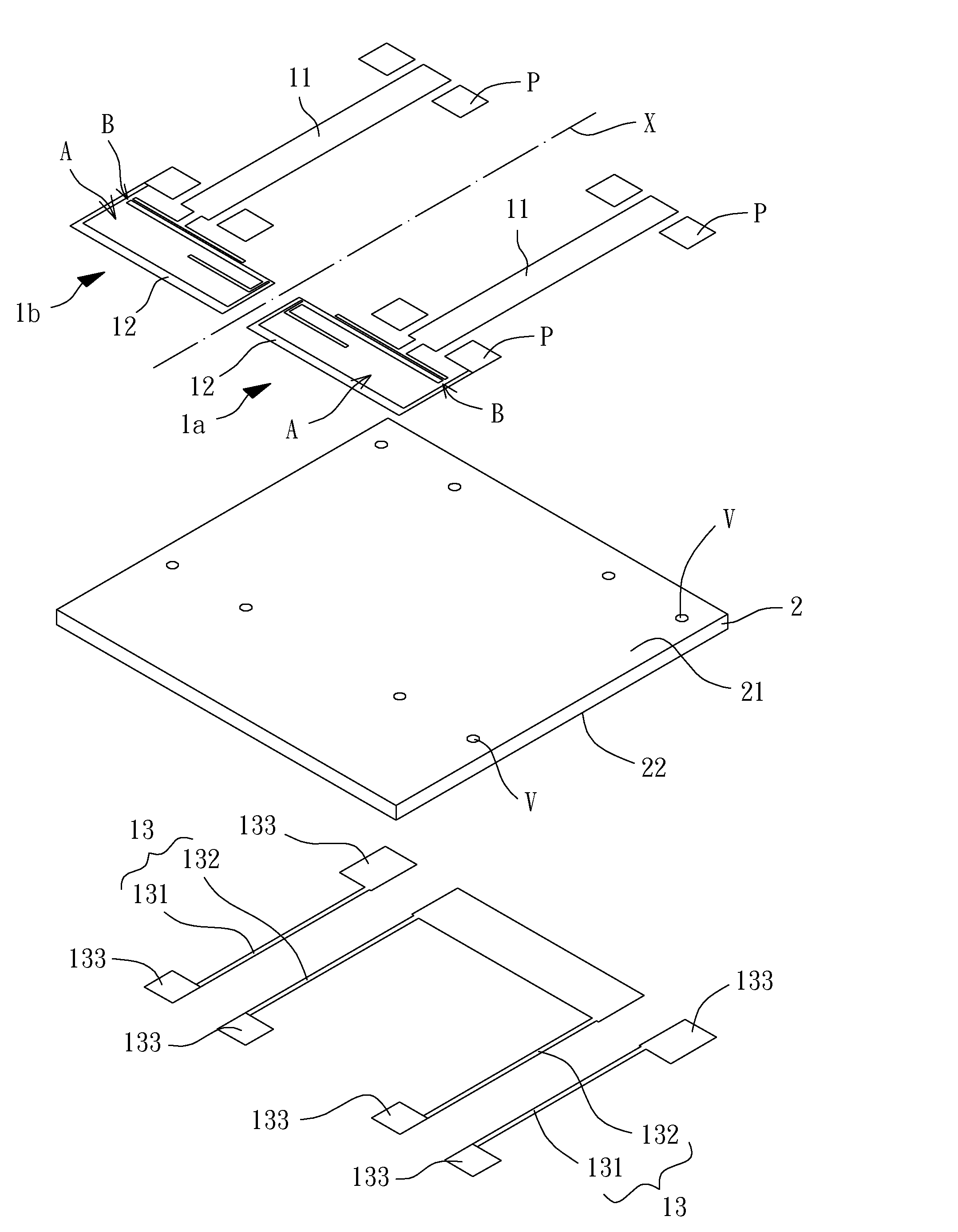
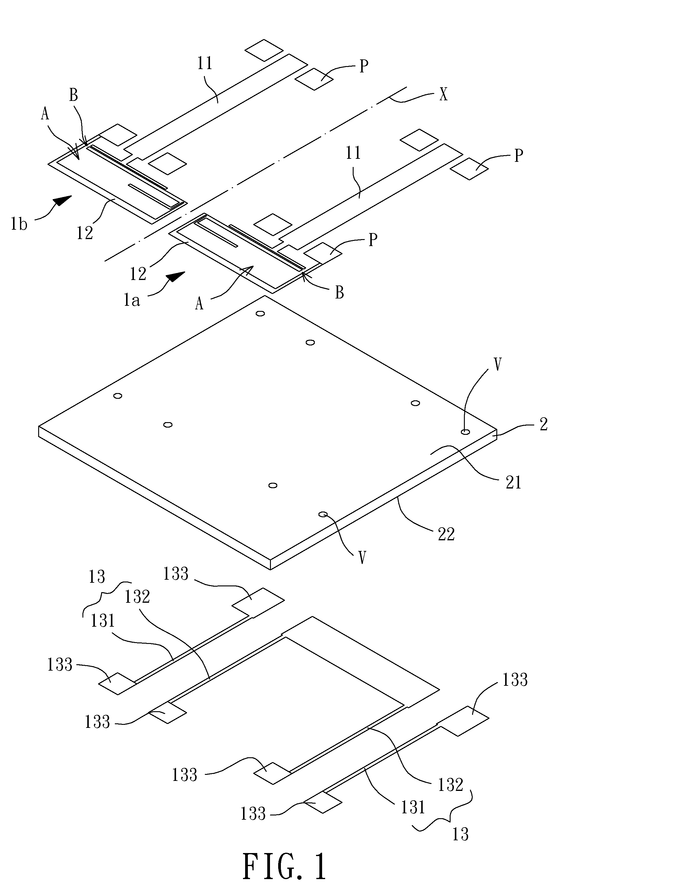
[0042]Referring to FIGS. 1 to 3, a MIMO antenna device is disclosed according to a preferred embodiment of the invention. The MIMO antenna device includes a plurality of antennas 1 and a substrate 2. Any two adjacent antennas 1 of the plurality of antennas 1 are symmetric with respect to an axis X. The antennas 1 can be disposed on the substrate 2. The substrate 2 is made of insulation material such as polyimide and comprises two opposite surfaces 21 and 22 for placement of the antennas 1.

[0043]The antennas 1 are made of material with electricity conductivity, such as metal. The antennas 1 are shown to consist of two antennas 1a and 1b in the embodiment for illustration purposes. However, the antennas 1 may include an even or odd number of antennas 1. Under the specific layout of the antennas 1 shown in FIG. 1, the two antennas 1a and 1b have low correlation and high isolation therebetween, as elaborated later in the specification.

[0044]Each antenna 1 has a T-shaped feeding unit 11,...


PUM


Abstract

A multi-input and multi-output antenna device is disclosed. The MIMO antenna device comprises two antennas symmetrically disposed on a substrate. Each antenna comprises a T-shaped feeding unit, a radiation unit and a ground unit. The T-shaped feeding unit and the radiation unit are disposed on a first surface of the substrate. The T-shaped feeding unit forms a strip portion and a top portion. The radiation unit has first and second ends. The radiation unit extends from the first end to the second end to form a rectangular region and a spacing. The first end extends parallel to the top portion. The ground unit is disposed along two sides of the strip portion and electrically coupled to the second end. The two strip portions of the two T-shaped feeding units are parallel to and aligned with each other. The two ground units are electrically connected to each other.

Description

BACKGROUND OF THE INVENTION[0001]1. Field of the Invention[0002]The present invention generally relates to a MIMO antenna device and an antenna package having the MIMO antenna device and, more particularly, to a MIMO antenna device that includes two antennas having a low correlation between the two antennas, as well as an antenna package having the MIMO antenna device.[0003]2. Description of the Related Art[0004]System in Package (SiP) technology has been widely used in multi-mode wireless communication products to integrate semiconductor chips with passive elements. As an example, passive elements such as electronic circuits, antennas and connectors are integrated as an integrated passive device (IPD) via semiconductor manufacturing technology.[0005]As the demanded wireless transmission data rates continue to grow in the latest wireless communication technologies, such as Long-term evolution (LTE) and WiMAX, the conventional single-input and single-output (SISO) antenna technology ...

Claims


Application Information

Patent Timeline
IPC IPC(8): H01Q21/28H01Q21/00
CPCH01Q21/28H01Q21/0075H01L2223/6677H01L2224/16225H01L2924/19107H01Q9/0442H01Q9/045
Inventor LIN, KEN-HUANGHORNG, TZYY-SHENGTANG, TZU-CHUN
Owner NAT SUN YAT SEN UNIV
Learn More