Image forming apparatus

Active Publication Date: 2018-11-22
BROTHER KOGYO KK
View PDF0 Cites 0 Cited by
  • Summary
  • Abstract
  • Description
  • Claims
  • Application Information

AI Technical Summary

Benefits of technology

The present invention relates to an image forming apparatus that can prevent malfunctions caused by external light reaching the photosensor, while still being compact and efficient. The technical effect of the invention is to provide a casing with a first opening, a door movable between a closing position to close the first opening and an opening position to open the first opening, and a cartridge detachably attached to, through the first opening, an attachment position defined between the first frame and the second frame. A light shielding part is provided to guide the cartridge towards the attachment position, and a second guiding part is provided to guide the cartridge towards the attachment position. This design prevents external light from entering the casing and reaching the photosensor, while still allowing the cartridge to be easily attached and detached.

Problems solved by technology

If such external light reaches the light receiver, the photosensor may malfunction.

Method used


Image

  • Image forming apparatus
  • Image forming apparatus
  • Image forming apparatus

Examples


Embodiment Construction

[0025]Hereinafter, referring to the accompanying drawings, an embodiment of the present disclosures will be described.

[0026]

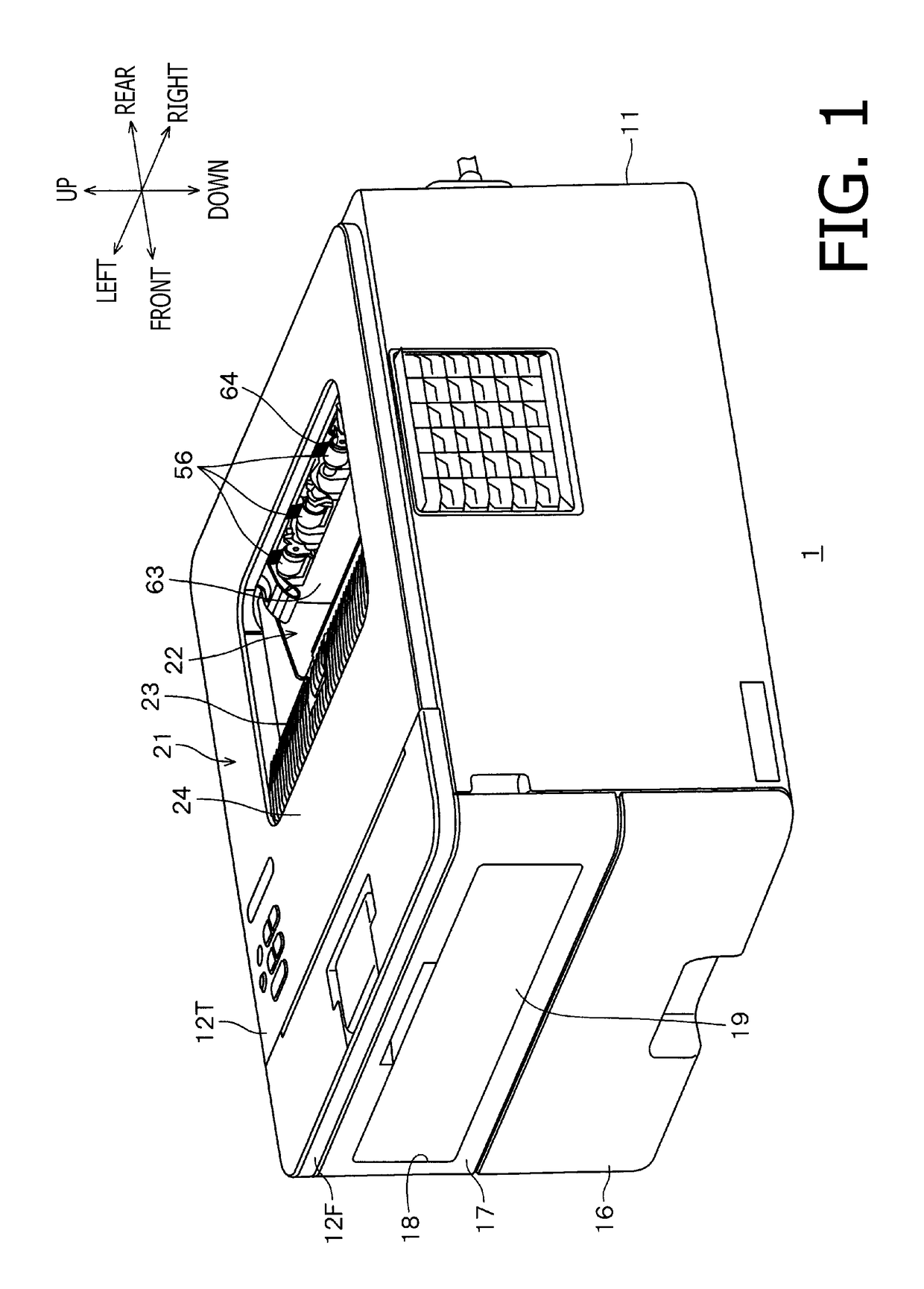
[0027]FIG. 1 is a perspective view of a printer 1 according to an embodiment of the present disclosures. The printer 1 is a monochromatic laser printer, which is an example of an image forming apparatus.

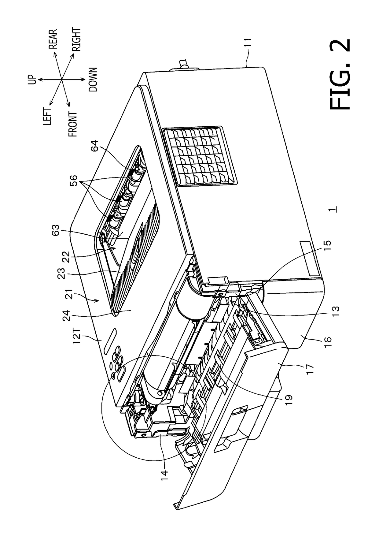
[0028]The printer 1 has a casing 11 configuring an outer appearance of the printer 1. The casing 11 has a substantially rectangular parallelepiped shape. The casing 11 has a first opening 13 which extends over one side surface 12F and an upper surface 12T as shown in FIG. 2.

[0029]Hereinafter, for the sake of description, front, rear, right and left sides are defined as follows. A side where the first opening 13 is defined as the front side of the printer, and an opposite side of the printer 1 is defined as the rear side. Thus, the one side surface 12F is the front surface of the casing 11. When the printer 1 is viewed from the front side, the right and left side...


PUM


Abstract

An image forming apparatus has a first opening on a side surface of the casing, first and second frames, a cartridge detachably attached through the first opening, and light receiver and light emitter respectively provided to the first and second frames. The cartridge shields the light from the light emitted when attached to an attachment position. The first and second frames face across the attachment position. The light reaches the light receiver when the cartridge is detached from the casing. A door is movably secured to the casing between closing and opening positions, and a second opening allowing a sheet to pass through is formed on the door. External light entering through the second opening and directed toward the light receiver is shielded by a light shielding part provided to the first frame, which also serves as a guiding part to guide attachment of the cartridge.

Description

CROSS-REFERENCE TO RELATED APPLICATIONS[0001]This application claims priority under 35 U.S.C. § 119 from Japanese Patent Application No. 2017-097799 filed on May 17, 2017. The entire subject matter of the application is incorporated herein by reference.BACKGROUNDTechnical Field[0002]The present disclosures relate to an image forming apparatus.Related Art[0003]Conventionally, there has been known a cartridge type image forming apparatus which is configured such that a cartridge is detachably attached inside a main body of the image forming apparatus. The cartridge is configured such that, for example, a photosensitive drum and a developing roller configured to supply toner to the photosensitive drum to form a toner image are integrally held by a frame.[0004]In the cartridge type image forming apparatus, typically, an opening is formed on a front surface of the main body, and a front door for opening / closing the opening is provided. When the front door is opened, the opening is expose...

Claims


Application Information

Patent Timeline
IPC IPC(8): G03G21/18
CPCG03G21/18G03G15/0856G03G15/04036G03G15/6555G03G21/1633G03G21/1842G03G21/1896
Inventor YOSHIMUNE, HIDEAKIMIZUNO, TOMOYUKISAEKI, MASAHITOYAMAMOTO, TOMOYA
Owner BROTHER KOGYO KK
Why Eureka
Try Eureka