
Perforated armor plates

a technology of armor plates and perforations, applied in the field of multi-layer ballistic armor, can solve the problem of reducing the residual penetration capability of basic armor by a substantial amoun

Inactive Publication Date: 2006-09-28
PLASAN SASA AGRI COOP SOC
View PDF14 Cites 48 Cited by
  • Summary
  • Abstract
  • Description
  • Claims
  • Application Information

AI Technical Summary

Benefits of technology

[0009] Destabilization (of a projectile) is loss of stable orientation of the projectile axis along the flight trajectory as a result of a non symmetrical impact with a layer of material. The destabilization is measured by the yaw angle between the projectile longitudinal axis and the direction of the flight trajectory. The yaw angle increases the stopping power effectiveness of the armor system especially when the yaw angle exceeds 5°.
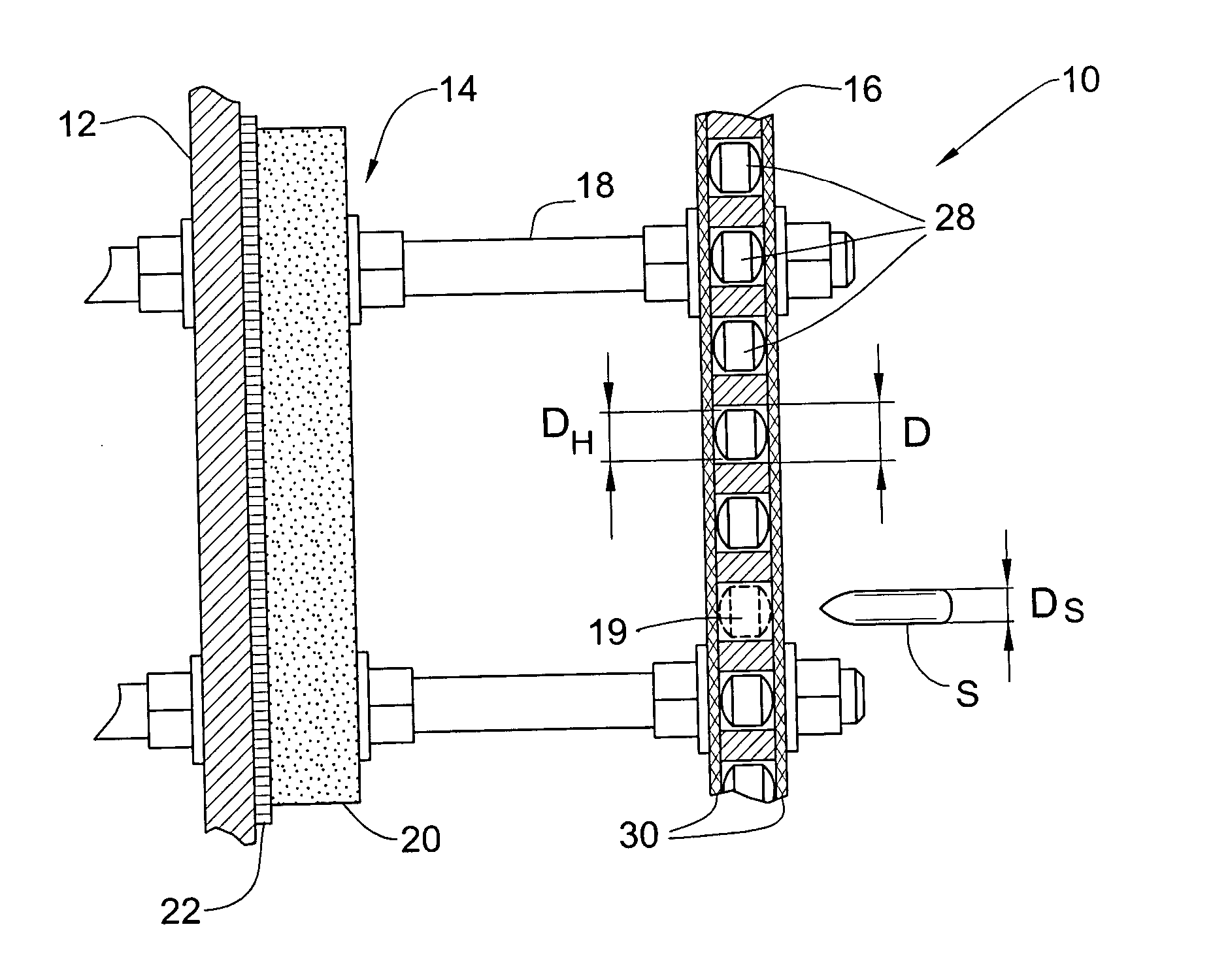
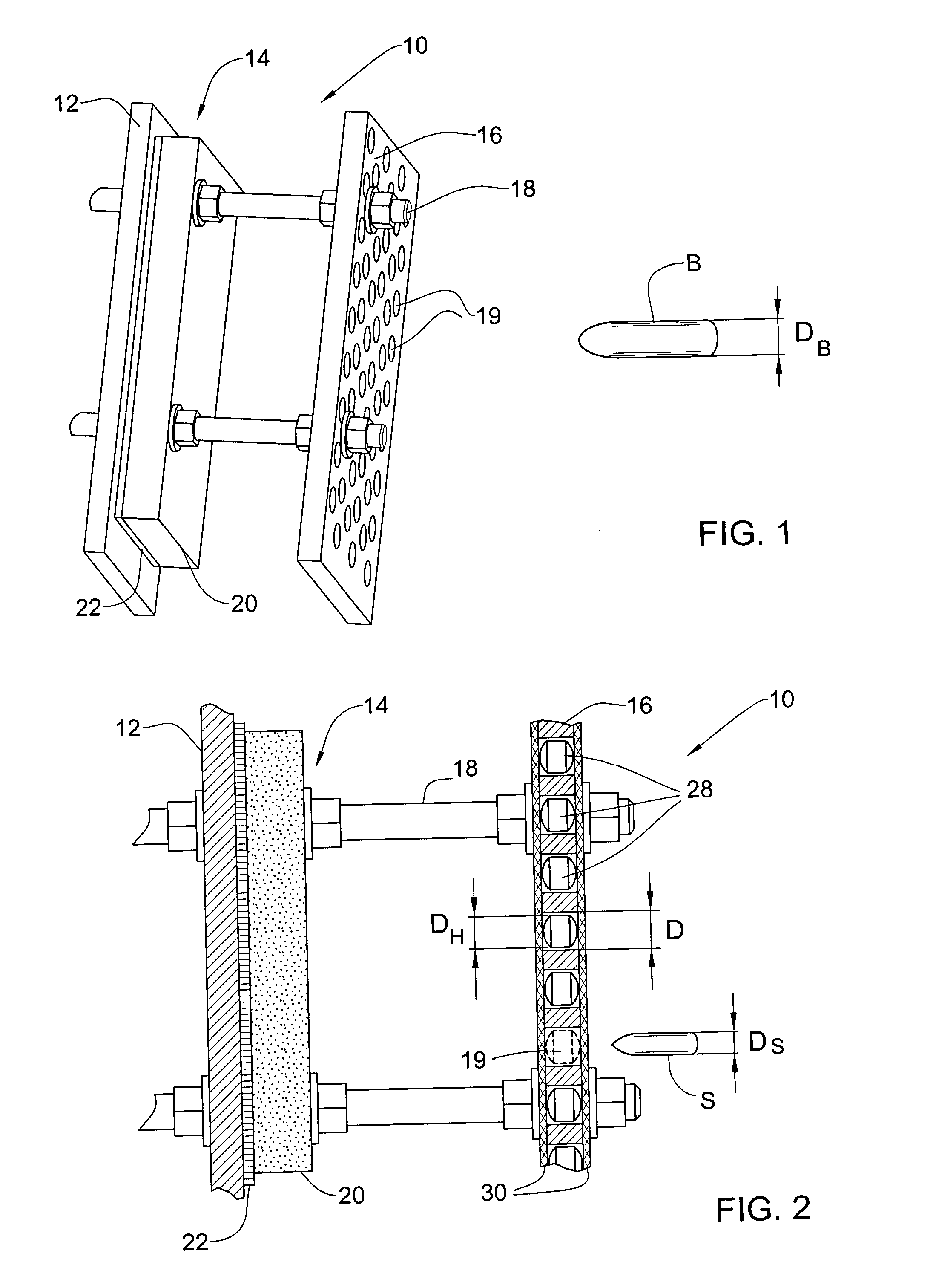
[0015] In accordance with one aspect of the present invention, there is provided a system of armor plates for protection of a structure such as a vehicle against projectiles B and S of two characteristic calibers DB and DS, DB being larger than DS. The system comprises a main armor plate and an auxiliary armor plate mounted in front of the main armor plate at a distance L therefrom. The auxiliary plate is perforated with through holes of characteristic diameter D, D being larger than DS up to about 1.2 DB. At least one hard-material body is fixed in each of the holes, so as to provide at least destabilization of impacting projectiles S or B capable of free passage through an unobstructed hole of diameter D when striking close to the hole center.
[0024] The invention may be applied to various types of military vehicles and may provide combined ballistic protection against projectiles of different diameters ranging, for example from 7.62 mm, 0.5″ (12.7 mm), to 14.5 mm or even to 20 mm.
[0025] The armor having the main and auxiliary plates according to the present invention may have a lighter weight than the weight it would need to have in order to provide the same level of ballistic protection, if the armor consisted only of one plate or if the auxiliary plate had only through openings. Moreover, when used as an add-on armor on a vehicle's basic structure, the auxiliary armor plate of the present invention may allow a smaller distance to the basic structure, than the distance it would need to have for the same level of ballistic protection, with single plate armor of the same weight (perforated or not).
[0028] the spacing between the auxiliary and the main plates, which allows the deflected projectile trajectory or destabilized projectile attitude to further deviate from a normal impact on the main plate, or allows the projectile's parts to be more separated in space between their impact on the main plate.

Problems solved by technology

The use of those plates is mainly to effectively break an incoming projectile or at least to divert it from its incident trajectory and thus substantially reduce its residual penetration capability through the basic armor.

Method used


Image

  • Perforated armor plates
  • Perforated armor plates

Examples


Embodiment Construction

[0032] An armor system 10 schematically shown in FIGS. 1 and 2 is an example of ballistic armor of the present invention designed for ballistic protection of a basic structure, e.g. side wall 12 of a vehicle, against two kinds of ballistic threats, for example, large caliber bullets B and smaller caliber bullets S.

[0033] The armor 10 comprises a main armor plate 14 and an auxiliary armor plate 16 located in front of the main armor plate 14. The plates 14 and 16 are attached to the side wall 12 by attachment means such as bolts 18 as shown in FIG. 1. Alternatively, the main armor plate 14 may be attached to the side wall 12 by one attachment means, and the auxiliary plate 16 may be attached to the main plate 14 or to the side wall by another attachment means. The attachment means are designed to keep the plates at a predetermined fixed distance (stand-off) from each other.

[0034] The main armor plate 14 is designed to stop alone, or together with the side wall 12 but without the aux...


PUM


Abstract

A system of armor plates is adapted for protection of a structure against projectiles B and S of two characteristic calibers DB and DS, DB>DS. The system compres a main armor plate and an auxiliary plate mounted in front of the main armor plate at a distance therefrom. The auxiliary plate comprises a plate made of ballistic material and perforated with through holes of characteristic diameter D, 1.2 DB>D>1.2 DS. At least one hard-material body of diameter DH is disposed in each of the holes, such that the auxiliary plate provides at least destabilization of impacting projectiles S capable of free passage through an unobstructed hole of diameter D.

Description

FIELD OF THE INVENTION [0001] This invention relates to multi-layer ballistic armor and, particularly, to armor plates suitable for use as add-on (exterior) armor for military vehicles. BACKGROUND OF THE INVENTION [0002] Perforated or slit armor plates are in use for many years in armor systems where they are installed at some stand-off distance from the vehicle's basic armor. The use of those plates is mainly to effectively break an incoming projectile or at least to divert it from its incident trajectory and thus substantially reduce its residual penetration capability through the basic armor. The total weight of such armor system is considerably less than the weight of a basic armor with the same antiballistic capability. Usually the holes or slits are designed to interact with the characteristic diameter of the threat (projectile caliber), and the performance effectiveness of such armor under impact is dominated by the plate material and thickness. [0003] U.S. Pat. No. 5,014,593...

Claims


Application Information

Patent Timeline
Patent Type & Authority Applications(United States)
IPC IPC(8): F41H5/00
CPCF41H5/013F41H5/023F41H5/0414F41H5/0492
Inventor RAVID, MOSCHEHIRSCHBERG, YOAV
Owner PLASAN SASA AGRI COOP SOC
Learn More