Microwave applicator system
a technology of applicators and microwaves, applied in microwave heating, electric heating, electric/magnetic/electromagnetic heating, etc., can solve the problems of inability to efficiently coupling small loads, inability to achieve efficient coupling for small loads, etc., to achieve strong reduction of microwave propagation through load, improve overall heating pattern, and reduce the height of the applicator
- Summary
- Abstract
- Description
- Claims
- Application Information
AI Technical Summary
Benefits of technology
Problems solved by technology
Method used
Image
Examples
first embodiment
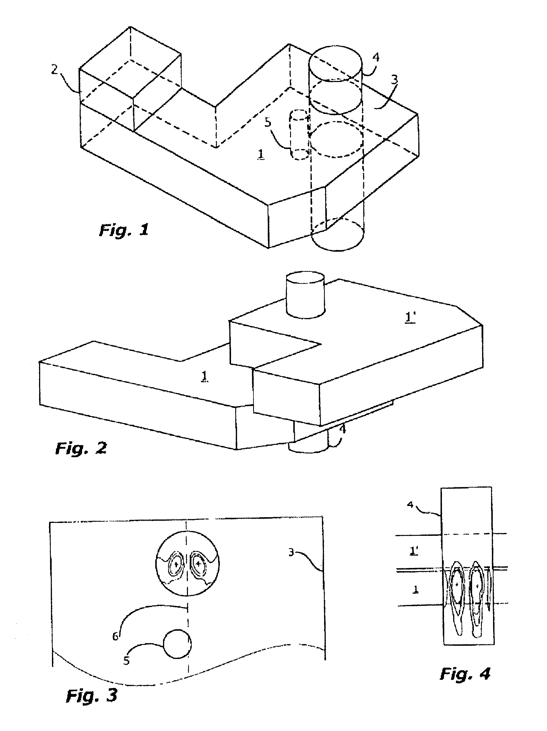
[0034]Referring now to the figures, and most particularly to FIG. 1, the present invention relates to a rectangular TE10 / TE20 mode applicator (or transducer) 1 with the generator 2 connected at the TE10 section. The TE20 section being closed by a shorting metal wall 3, and a cylindrical load 4 is located approximately at the centreline of the TE20 section. A tuning means 5 (here in the form of a rod) extends the whole way between the top and bottom surfaces in the TE20 section.
[0035]The applicator is air-filled and made up from metal walls according to well-established manufacturing technique for microwave applicators. In the case of a pure TE20 mode, the load location at the centreline provides the desired cylindrical TM1 field in the load. The rod 5 (preferably made from a metal) may then not be needed to obtain a symmetrical heating pattern in the load. However, it is of interest to provide a compact design, so in particular the TE20 section is quite short. The rod is then very c...
second embodiment
[0039]According to a first aspect of the invention the energy coupling between adjacent 90° displaced applicators by the load field may be made very small, so that the so-called crosstalk between such applicators will be very small, even if the associated generators are simultaneously excited.
[0040]According to a second aspect of the second embodiment the applicator 1 is designed so that it also works as a choke for the propagating fields from a first applicator through the load to a second applicator. An example of this is shown in FIG. 4, where only the lower applicator 1 is energised, and there is a second applicator 1′ just above but none below the first applicator. Actually, this feature is closely related to the first aspect of the second embodiment mentioned above. For efficient choking to be possible, it is necessary that a significant part of the microwave energy is bound to the load 4 is outside it. This may be the case for the TM1 mode type, but is not for the TM0 type mo...
third embodiment
[0042]the present invention relates to the design and use of multiple, low and closely stacked applicators to achieve high power densities in elongated or moving loads. The TE20 mode can in theory exist in a waveguide with arbitrarily small height, but there are of course practical limitations by the fact that the waveguide (integrated) impedance is proportional to its height, requiring a very large transformation ratio from the typically standard height of between a quarter and a half free space wavelength at magnetron generator transition to the TE10 portion.
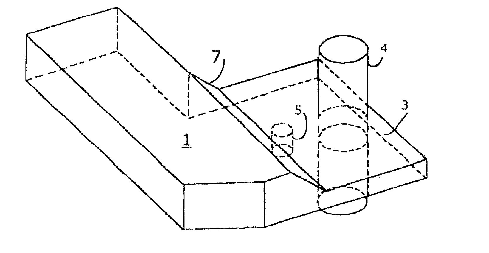
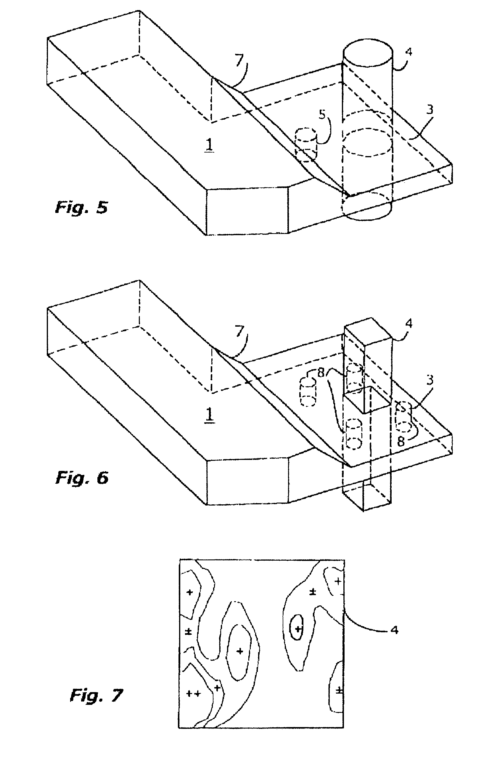
[0043]There are, however, generally no problems when the height is changed in one short step 7 as shown in FIG. 5, by a factor of up to 3. This is then normally in the TE20 section as shown in the same figure. The step can also be used to improve the choking function, as described for the overall length of the TE20 section for the second embodiment of the present invention.
[0044]An important aspect of the present invention in ...
PUM
 Abstract
Description
Claims
Application Information
 - R&D
- Intellectual Property
- Life Sciences
- Materials
- Tech Scout
- Unparalleled Data Quality
- Higher Quality Content
- 60% Fewer Hallucinations
Browse by: Latest US Patents, China's latest patents, Technical Efficacy Thesaurus, Application Domain, Technology Topic, Popular Technical Reports.
© 2025 PatSnap. All rights reserved.Legal|Privacy policy|Modern Slavery Act Transparency Statement|Sitemap|About US| Contact US: help@patsnap.com


