
Heater with simultaneous hot spot and mechanical intrusion protection

a technology of hot spot detection and mechanical intrusion protection, which is applied in the direction of ohmic resistance heating, heating element shapes, electrical appliances, etc., can solve the problems of severe scorching of heating products, fire, and inability of heating cables to have inherent thermal cut-off capabilities, so as to prevent or minimize current leakage, increase dielectric properties, and ensure safety. the effect of safety

Inactive Publication Date: 2005-10-25
THERMOSOFT INT
View PDF49 Cites 75 Cited by
  • Summary
  • Abstract
  • Description
  • Claims
  • Application Information

AI Technical Summary

Benefits of technology

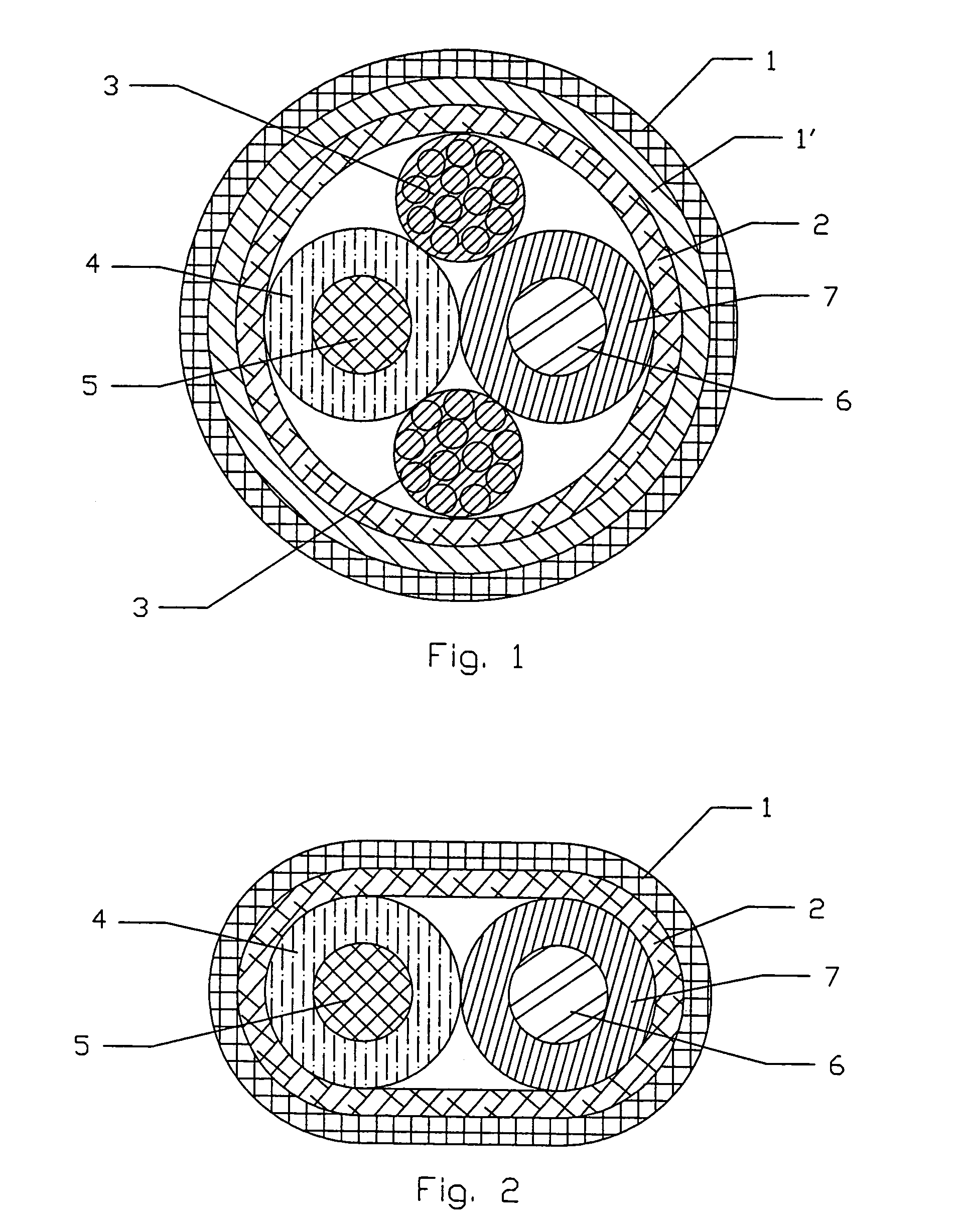
[0011]The second objective of the invention is to provide a significantly safe and more reliable heater which can function properly after it has been subjected to folding, kinks, punctures or crushing. In order to achieve the second objective, the heater of the present invention may comprise (a) electrically conductive threads / fibers and / or metal wires or combination thereof, and (b) multi-layer insulation of the whole heating cable. The electrically conductive fibers may be comprised of carbon, metal fibers, and / or textile threads coated with one or combination of the following materials: metal, carbon and / or electrically conductive ink. The multi-layer insulation of the electrically conductive threads / fibers provides increased dielectric properties, preventing or minimizing current leakage in the event of abuse of the heater. The insulation means may be applied in the form of encapsulation (through extrusion process) or lamination with insulating synthetic materials, having similar or different thermal and mechanical characteristics.

Problems solved by technology

Therefore, in the event of overheating of a very small surface area (hot spot) of the electric blanket or pad (for example, several square inches), the sensor may fail to detect a minor change of electrical resistance (due to operating resistance tolerance) in the long heating element.
In addition, such heating cable does not have inherent Thermal-Cut-Off (TCO) capabilities in the event of malfunction of the controller.
The disadvantage of this construction is that the final safety of the blanket relies on a complex NTC / meltdown detection system located in the controller.
In the event of controller failure, or significant delays in the detection of the NTC layer meltdown, severe scorching of the heating product or a fire can occur.
Such passive PTC sensing conductor needs an additional pair of lead wires going from the heater to the sensing control system, which increases weight, size and cost of the heating systems.
Another disadvantage of Gerrard's invention is that its control system utilizes a half-wave power cycle for heating and another half-wave power cycle for meltdown stroke detection in order to provide proper heating output and meltdown protection.
This feature becomes especially challenging for 120V and other lower voltage heating systems, compared to traditional European 240V systems.
Increased thickness of the heating wire leads to: (a) increased cost of the heating conductor; (b) increased overall size of the heating element and (b) increased heating wire susceptibility to breaking due to reduced flexibility.
The disadvantage of this system is that it requires at least two independent conductors connected to the control system.
The addition of heat sensing conductors for signal transfer and the addition of extra lead wires, results in increased size of the heating cable and lead wire cord, thereby reducing their flexibility and increasing their weight and cost.
Such mechanical intrusion may be in the form of moisture (water) penetration, heating element damage or direct electrical contact between the heating means and the ground conductor due to metallic intrusion inside the heating cable.

Method used


Image

  • Heater with simultaneous hot spot and mechanical intrusion protection
  • Heater with simultaneous hot spot and mechanical intrusion protection
  • Heater with simultaneous hot spot and mechanical intrusion protection

Examples


Embodiment Construction

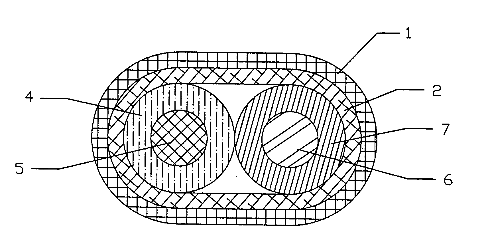
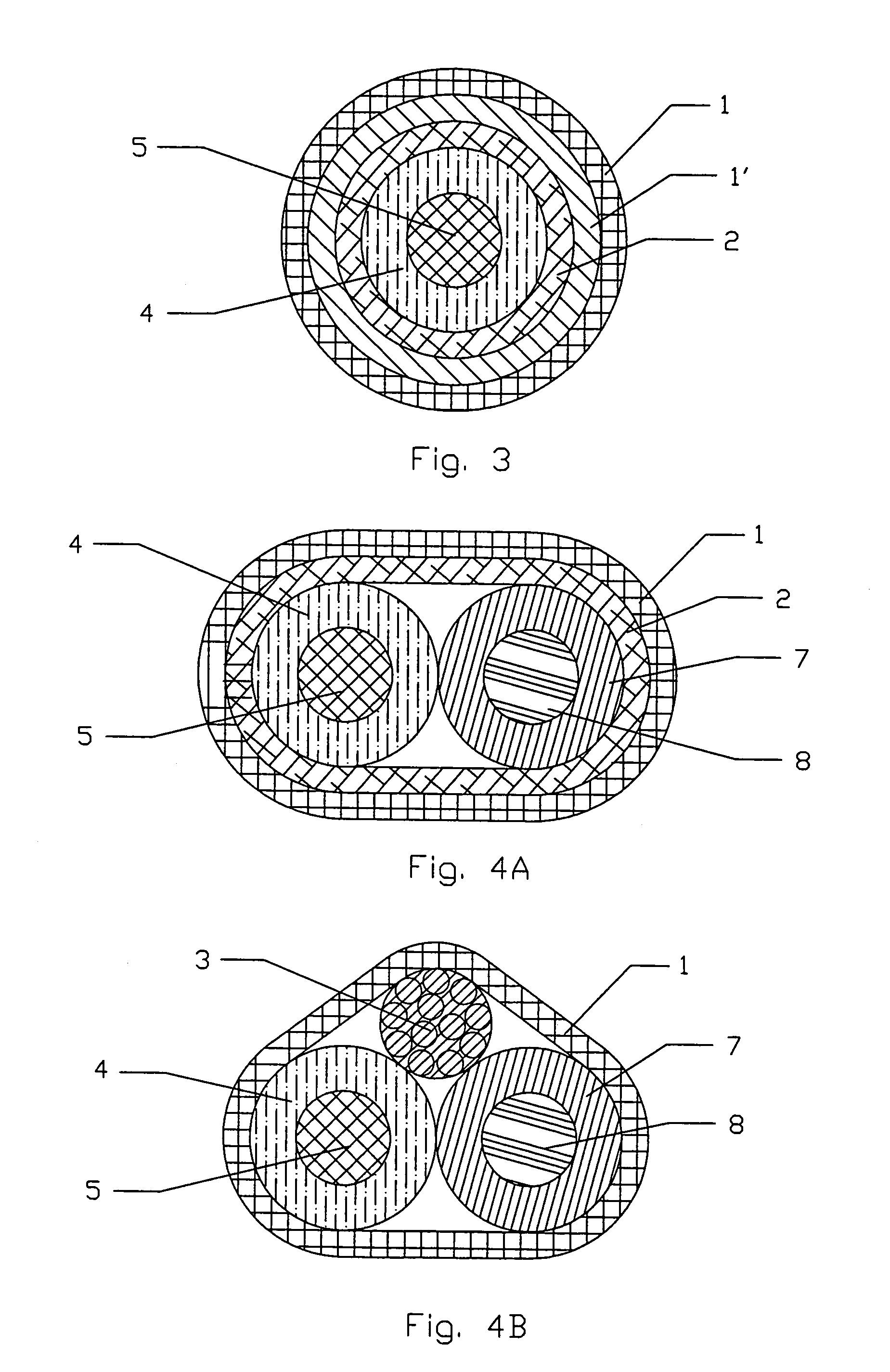
[0028]The invention consists of a heating element containing: (a) at least metal wires or metal / carbon containing textile fibers or combination thereof as heating means, insulated by at least one layer of NTC sensing means, (b) current leakage conductor, electrically connected with NTC sensing means and (b) at least one outer insulation of the heater. The invention describes a method of hot spot detection and overheating protection, using a combination of heating means, NTC layer, current leakage conductor and electronic controller, which detects the current imbalance between the live end and the neutral end of the heater.

[0029]The term “conductive means” or “conductor” described in this invention shall mean at least one of the following electrically conductive materials: metal wires, metal mesh or metal foil, electrically conductive textile fibers, electrically conductive polymers and other conductive materials, suitable for the purpose of this invention.

[0030]The term “heating mea...


PUM


Abstract

An electrical heater utilizes negative temperature coefficient material (NTC) and current imbalance between live and neutral ends of the heater to simultaneously protect the heater from the hot spot and mechanical intrusion into the heating cable. The NTC layer, separating the heating wire and current leakage conductor, becomes electrically conductive at the temperatures above 60° C., thus “leaking” the current to earth. The hot spot is detected by measuring the current imbalance between line and neutral connections of the heating cable. The mechanical intrusion into the heater, such as cable or insulation damage, water or sharp metal object penetration, is also simultaneously measured by the same current imbalance measuring system such as Ground Fault Circuit Interrupter (GFCI). The optional return conductor and metal foil / mesh hot spot detection shields cancel electromagnetic field. The heater may contain positive temperature coefficient (PTC) continuous sensor to control the temperature in the heater. Such PTC sensor can be made of electrically conductive fibers and / or metal wires.

Description

BACKGROUND OF INVENTION[0001]1. Field of Invention[0002]This invention relates to a method of hot spot detection and overheating protection of flexible electrical heaters, which have strong metal or carbon containing electrical conductors and insulation with semi-conductive temperature sensitive properties.[0003]2. Description of the Prior Art[0004]Heating elements have extremely wide applications in household items, construction, industrial processes, etc. Their physical characteristics, such as thickness, shape, size, strength, flexibility and other characteristics affect their usability in various applications.[0005]Numerous types of thin and flexible heating elements have been proposed. For example, U.S. Pat. No. 5,861,610 to John Weiss describes the heating wire, which is formed with a first conductor for heat generation and a second conductor for sensing. The first conductor and a second conductor are wound as coaxial spirals with an insulation material electrically isolating ...

Claims


Application Information

Patent Timeline
IPC IPC(8): H05B3/44H05B3/42H05B3/50H05B3/56
CPCH05B3/56H05B2203/019
Inventor KOCHMAN, ERICGERRARD, GRAHAMEKOCHMAN, DMITRY
Owner THERMOSOFT INT
Learn More