
Golf club head having a striking face with improved impact efficiency

Inactive Publication Date: 2005-09-27
CALLAWAY GOLF CO
View PDF9 Cites 29 Cited by
  • Summary
  • Abstract
  • Description
  • Claims
  • Application Information

AI Technical Summary

Benefits of technology

[0008]When a golf club head strikes a golf ball, large impact forces are produced that load a face section, also called a striking plate, of the golf club head. Most of the energy is transferred from the golf club head to the golf ball; however, some energy is lost as a result of the impact. The present invention comprises a golf club striking plate material and geometry having a unique combination of material properties for improved energy efficiency during impact with the golf ball.
[0010]By allowing the golf club head to flex and “cradle” the golf ball during impact, the contact region as well as contact time between the golf ball and the striking plate of the golf club head are increased, thus reducing the magnitude of the internal golf ball stresses as well as the rate of the stress build-up. This results in smaller golf ball deformations and lowers deformation rates, both of which produce much lower energy losses in the golf ball during impact. The static flexibility is inversely proportional to the striking plate stiffness, while the dynamic flexibility is inversely proportional to square of the striking plate bending natural frequency. In other words, a decrease in plate stiffness will cause the static flexibility to increase, while doubling the plate bending natural frequency will reduce dynamic flexibility to a level ¼ of the original striking plate. Increasing the static or dynamic flexibility can be accomplished via several different configurations for the golf club head: altering geometry of the face section; altering attachment of the striking plate to the club-head body; reducing the thickness of the striking plate; or through the innovative use of new structural materials having reduced material stiffness and / or increased material density. Material strength of the striking plate of the golf club head in conjunction with impact load from contact with the golf ball determines the minimum required thickness for the face section. The greater the available material strength, the thinner the striking plate can be, and thus greater the flexibility. So the material properties that control static and dynamic flexibility are decreased compression stiffness, increased density, and increased strength. The present invention specifies which face materials and static / dynamic flexibilities provide improved energy conservation during impact of the golf club head and the golf ball. Materials used in the face section of the golf club head constitute an additional important factor in determining performance characteristics of coefficient of restitution (COR), launch angle, spin rate and durability.
[0011]One object of the present invention is to improve impact efficiency between a golf club head and the golf ball.
[0012]Another object is to designate a range of material properties to increase the static flexibility, otherwise described as reduced bending stiffness, of the striking plate of the golf club head. Any number of materials having requisite limitations of stiffness and strength can be utilized in the manufacture of the golf club of the present invention to produce a compliant, or softer flexing performance during impact with the golf ball.
[0013]Another object is to designate a range of material properties to increase the dynamic flexibility, otherwise described as reduced bending natural frequency, of the striking plate of the golf club head. Any number of materials having requisite limitations of stiffness and strength can be utilized in the manufacture of the golf club of the present invention to produce a compliant, or softer flexing performance during impact with the golf ball.

Problems solved by technology

Most of the energy is transferred from the golf club head to the golf ball; however, some energy is lost as a result of the impact.
In other words, a decrease in plate stiffness will cause the static flexibility to increase, while doubling the plate bending natural frequency will reduce dynamic flexibility to a level ¼ of the original striking plate.

Method used


Image

  • Golf club head having a striking face with improved impact efficiency
  • Golf club head having a striking face with improved impact efficiency
  • Golf club head having a striking face with improved impact efficiency

Examples


Embodiment Construction

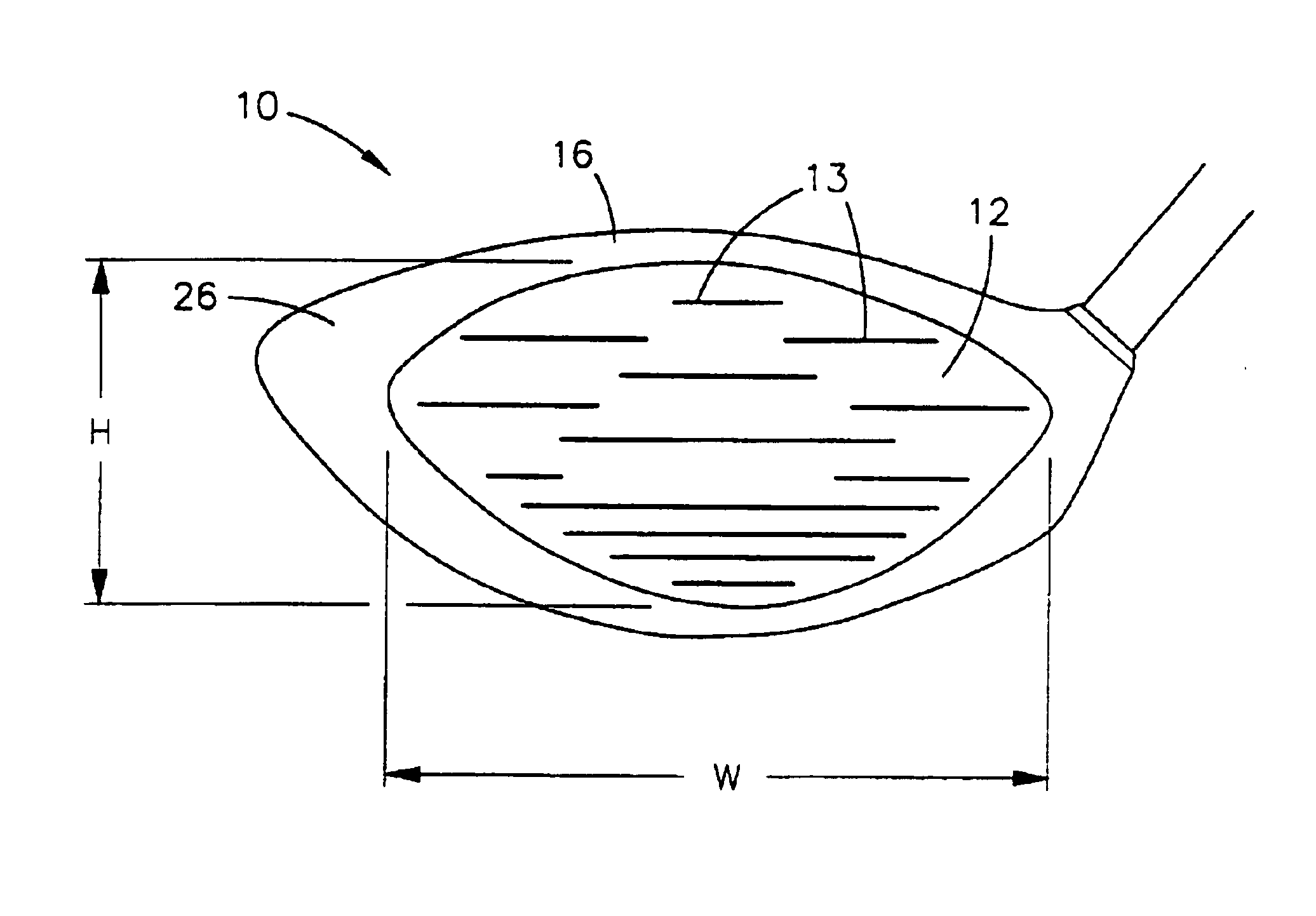
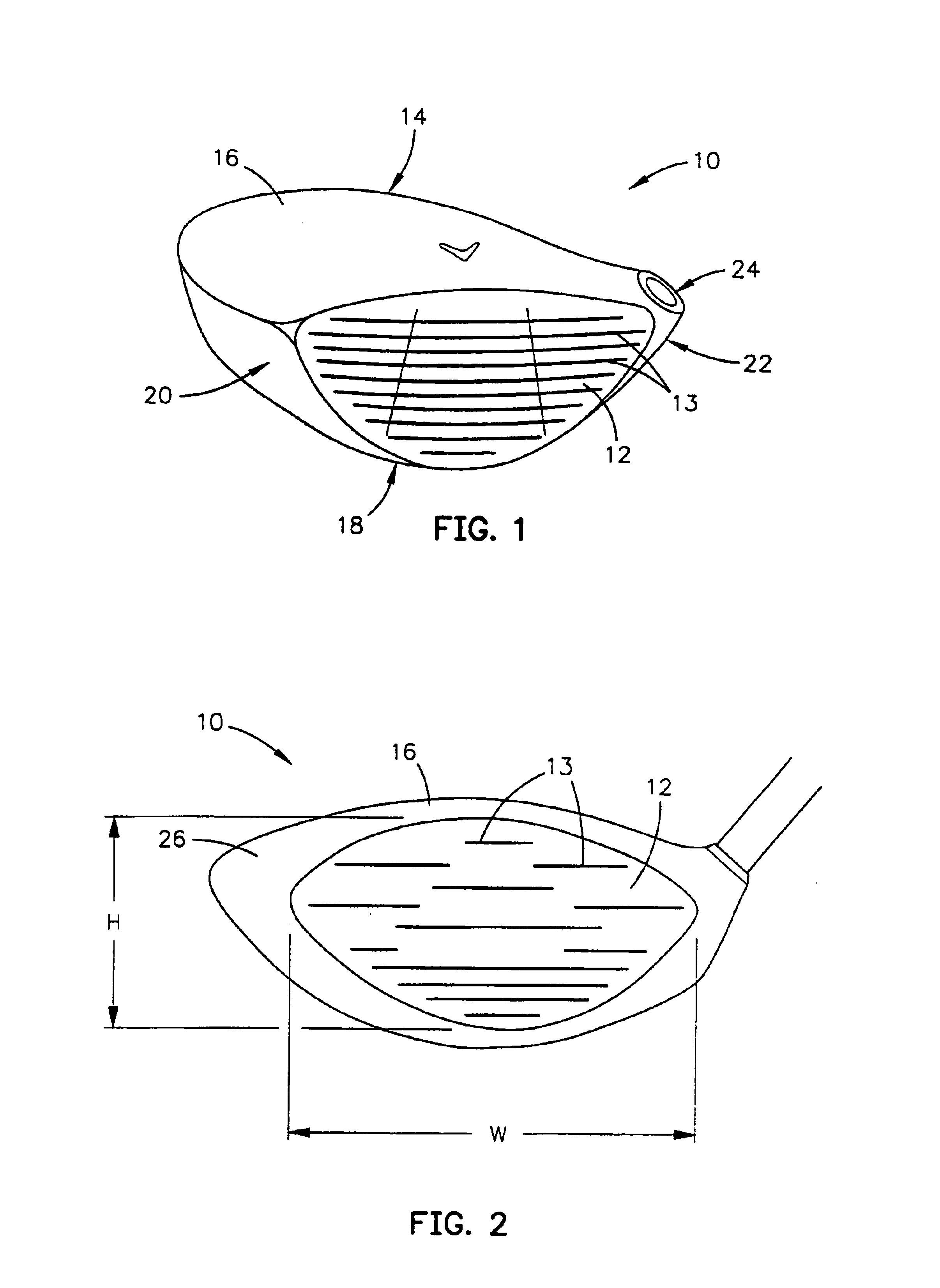
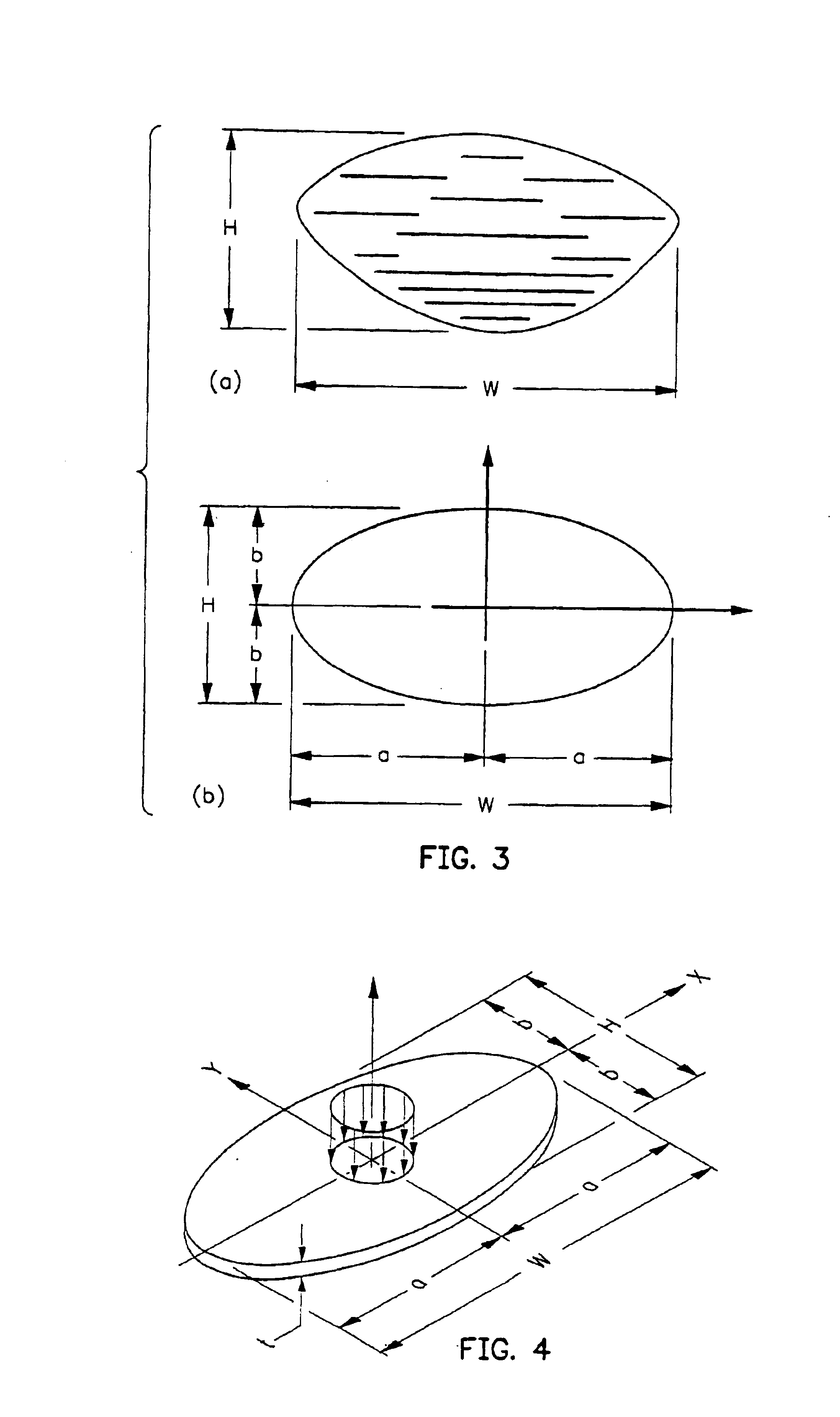
[0033]As shown in FIG. 1 a wood-type golf club head 10 comprises a face section 12, a rear section 14, a top section 16, a bottom section 18, a toe section 20, a heel section 22 and a hosel inlet 24 to accept a golf shaft (not shown). The golf club head 10 is a unitary structure which may be composed of two or more elements joined together to form the golf club head 10. The face section 12, also called a striking plate, is an impact surface for contacting a golf ball (not shown). Structural material for the golf club head 10 can be selected from metals and non-metals, with a face material exhibiting a maximum limit for face stiffness and natural frequency being a preferred embodiment.

[0034]The present invention is directed at a golf club head 10 having a striking plate 12 that makes use of materials to increase striking plate flexibility so that during impact less energy is lost, thereby increasing the energy transfer to the golf ball. This increased energy transfer to the golf ball...


PUM


Abstract

A compliant golf club head permits a more efficient impact between a golf ball and the golf club head. Material and geometry constraints of a striking plate of the golf club head can reduce energy losses caused by large strain and strain rate values of the golf ball, these constraints on the striking plate yield a measure of the impact efficiency of the golf club head. Designating a required natural frequency range of the striking plate provides improved impact efficiency between the golf ball the golf club head.

Description

CROSS REFERENCES TO RELATED APPLICATIONS[0001]This application is a continuation application of U.S. patent application Ser. No. 10 / 250,194, filed on Jun. 11, 2003, now U.S. Pat. No. 6,685,576, which is a continuation application of U.S. patent application Ser. No. 10 / 065,690, filed on Nov. 8, 2002, now U.S. Pat. No. 6,669,579, which is a continuation application of U.S. patent application Ser. No. 09 / 683,799, filed on Feb. 15, 2002, now U.S. Pat. No. 6,478,692, which is a continuation-in-part application of U.S. patent application Ser. No. 09 / 525,216 filed on Mar. 14, 2000, now U.S. Pat. No. 6,348,015,STATEMENT REGARDING FEDERALLY SPONSORED RESEARCH OR DEVELOPMENT[0002]Not ApplicableBACKGROUND OF THE INVENTION[0003]1. Field of the Invention[0004]The present invention relates to a golf club head. More specifically, the present invention relates to a face section of a golf club head to reduce energy losses when impacting a golf ball.[0005]2. Description of the Related Art[0006]Techni...

Claims


Application Information

Patent Timeline
IPC IPC(8): A63B53/04
CPCA63B53/04A63B53/0466A63B2053/0416A63B2053/0408A63B53/047A63B2209/00A63B53/0408A63B53/0416A63B60/00
Inventor KOSMATKA, JOHN B.
Owner CALLAWAY GOLF CO
Learn More