
Point of care diagnostic systems

a diagnostic system and point of care technology, applied in the field of point of care diagnostic systems, can solve the problems of large subjectivity involved and significant variance among those interpreting such tests, and achieve the effect of minimizing the error between images

Inactive Publication Date: 2005-08-30
CYTYC CORP
View PDF236 Cites 120 Cited by
  • Summary
  • Abstract
  • Description
  • Claims
  • Application Information

AI Technical Summary

Benefits of technology

"The patent describes systems and methods for diagnosing or risk assessing medical conditions by using data from point of care diagnostic tests. These systems are designed to be used at the point of care, such as in emergency rooms or doctor's offices, and can provide quick and accurate results. The systems include a reader and software for processing the test data, which can be used to determine the presence or concentration of a target analyte in a patient sample. This information can then be used to evaluate the risk of a medical condition or make a diagnosis. The systems can be automated and controlled using computer-based systems. Overall, the patent provides a solution for quickly and accurately diagnosing and assessing risks for medical conditions."

Problems solved by technology

As a result of the human perception and judgment involved, there is significant variance among those interpreting such test results as to whether a color change or other measurable signal has occurred and the degree of such occurrence.
Furthermore, there is a great deal of subjectivity involved in interpreting whether immunoassay results are positive or negative.

Method used


Image

  • Point of care diagnostic systems
  • Point of care diagnostic systems
  • Point of care diagnostic systems

Examples


example 1

Immunoassay Test Strip

[0280]A. The Test Strip

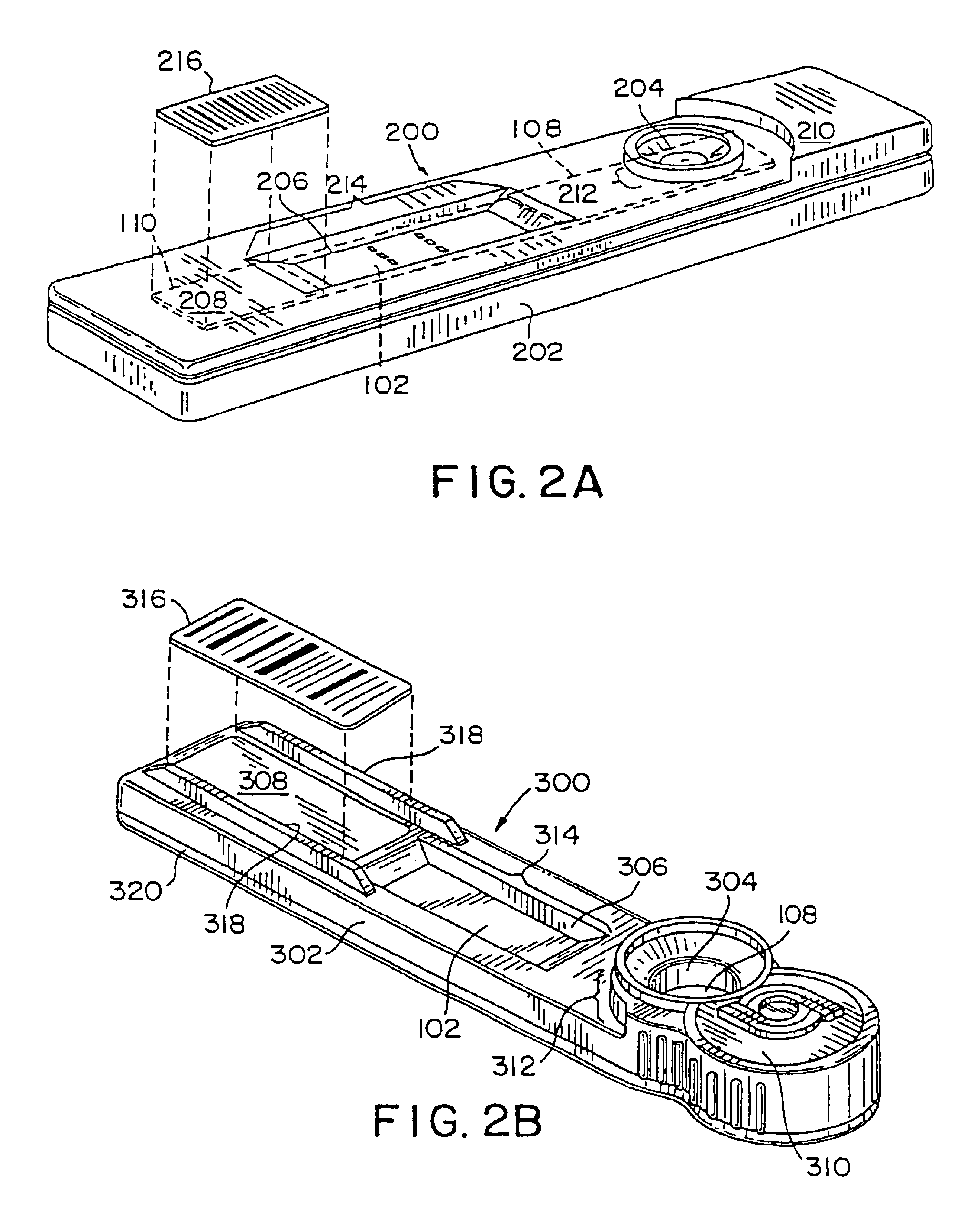
[0281]The test strip 100 includes a membrane system including three components: a porous or bibulous member 102; a conjugate pad 108; and an absorbent pad 110. The membrane system may be mounted on a substrate or backing 112, with the conjugate pad 108 and the absorbent pad 110 slightly overlapping the porous or bibulous member 102, which is interposed thereinbetween. As can be seen in FIGS. 1A and 1B, the conjugate pad 108 overlaps the porous or bibulous member 102 so that a fluid sample placed onto the conjugate pad 108 is communicated from the conjugate pad 108 to the porous or bibulous member 102. Similarly, the absorbent pad 110 overlaps with the porous or bibulous member 102 so that fluid samples introduced into the porous or bibulous member 102 from the conjugate pad 108 can then be transmitted to the absorbent pad 110. Thus, the conjugate pad 108, the absorbent pad 110 and the porous or bibulous member 102 are all in fluid communi...

example 2

Immunoassay Procedure

[0305]A. Colored Latex Label

[0306]In conducting the assay, the sample is extracted from a swab into antiprotease transfer buffer (0.05 M Tris buffer, pH 7.4, 1% BSA, 5 mM EDTA, 1 mM phenylmethylsulfonyl fluoride (PMSF), and 500 Kallikrein Units / ml of Aprotinin), heated for 15 min. at 37° C. and filtered through a large pore (25μ) plunger filter. A volume of 200 μl of test sample is then delivered to the conjugate pad at the application zone using a standard plastic pipet. Any fFN in the sample will bind to the labeled monoclonal antibody and the resulting complex migrates into the nitrocellulose strip. When the complex encounters the detection zone, the immobilized anti-FN antibody binds the complex, thereby forming a colored stripe due to the aggregation of the dye-containing latex beads. Any unbound latex-conjugated anti-fFN antibody continues to migrate into the control zone where it is captured by the immobilized goat anti-mouse antibody and thereby forms a ...

example 3

Operation of the Reflectance Reader

[0312]The test strip is read using the reflectance reader exemplified herein. This reader (described above) is adapted to read an immunochromatographic test strip supported within the housing. The reflectance reader includes a cassette slot for receiving the test-strip housing, and a sensing head assembly for reading the test strip supported within the test-strip housing using reflected light. The sensing head assembly includes a first light-emitting diode (LED1), a second LED (LED2), a silicon photodiode detector, and 39 optical fibers randomly arranged in a narrow slit (e.g., 0.020″ wide) located at the bottom of the sensing head assembly. LED1 emits light with a wavelength of 430 nm (blue), and LED2 emits light with a wavelength of 595 nm (amber). The optical fibers are arranged in three groups of 13 optical fibers each: the first group transmits light emitted by LED1 to the slit; the second group transmits light emitted by LED2 to the slit; and...


PUM

PropertyMeasurementUnit
timeaaaaaaaaaa
timeaaaaaaaaaa
distanceaaaaaaaaaa

Abstract

Systems and methods for medical diagnosis or risk assessment for a patient are provided. These systems and methods are designed to be employed at the point of care, such as in emergency rooms and operating rooms, or in any situation in which a rapid and accurate result is desired. The systems and methods process patient data, particularly data from point of care diagnostic tests or assays, including immunoassays, electrocardiograms, X-rays and other such tests, and provide an indication of a medical condition or risk or absence thereof. The systems include an instrument for reading or evaluating the test data and software for converting the data into diagnostic or risk assessment information.

Description

RELATED APPLICATIONS[0001]This application is a divisional of U.S. application Ser. No. 09 / 063,497, filed Apr. 20, 1998 now U.S. Pat. No. 6,394,952, Emory V. Anderson, Edward Nemec, Jerome Lapointe, Duane DeSieno, Ricardo Martinez, Gail Marzolf, Ronald Pong, Lynn Jones, Robert O. Hussa and Andrew Senyei, entitled “POINT OF CARE DIAGNOSTIC SYSTEMS”, and a continuation-in-part of U.S. application Ser. No. 09 / 017,901, filed Feb. 3, 1998 now U.S. Pat. No. 6,267,722 to Emory V. Anderson, Edward Nemec, Jerome Lapointe, Duane DeSieno, Ricardo Martinez, Gail Marzolf, Ronald Pong, Lynn Jones, Robert O. Hussa and Andrew Senyei, entitled “POINT OF CARE DIAGNOSTIC SYSTEMS.”[0002]This application is also related to U.S. application Ser. No. 08 / 599,275 to Jerome Lapointe and Duane DeSieno, filed Feb. 9, 1996, entitled “METHOD FOR DEVELOPING MEDICAL AND BIOCHEMICAL DIAGNOSTIC TESTS USING NEURAL NETWORKS”, now abandoned, copending U.S. application Ser. No. 08 / 798,306 to Jerome Lapointe and Duane De...

Claims


Application Information

Patent Timeline
Patent Type & Authority Patents(United States)
IPC IPC(8): G01N21/47G06F19/00G01N33/53G01N21/27G01N33/558G01N33/68G06Q50/00
CPCG01N21/474G01N21/8483G01N33/558G01N33/6887G01N33/689G06F19/321G06F19/345G06F19/3487G06F19/366G01N2333/78G01N2800/368G06F19/322Y10S436/811Y10S436/814G16H10/60G16H50/20G16H15/00G16H10/40G16H30/40Y02A90/10G01N33/54388
Inventor ANDERSON, EMORY V.LAPOINTE, JEROMEMARTINEZ, RICARDOMARZOLF, GAILPONG, RONALDJONES, LYNNHUSSA, ROBERT O.NEMEC, EDWARDSENYEI, ANDREW E.DESIENO, DUANE
Owner CYTYC CORP
Learn More