
Concentrator

Inactive Publication Date: 2005-02-01
DAICEL CHEM IND LTD
View PDF13 Cites 20 Cited by
  • Summary
  • Abstract
  • Description
  • Claims
  • Application Information

AI Technical Summary

Benefits of technology

is to provide a concentrator capable of concentrating an extract or raffinate from a simulated moving bed chromatographic apparatus to a concentrate of a predetermined concentration, constantly and automatically.
A still further objective of the invention is to provide a concentrator that is capable of producing a concentrate of a high concentration just after the operation of the simulated moving bed chromatographic apparatus started, and of maintaining a proper concentration of the concentrate even when the operational conditions of the apparatus are changed.

Problems solved by technology

Because such mixtures of optical isomers are often vulnerable to heat, film heaters such as falling film evaporators (FFE) and wiped film evaporators (WFE) are commonly employed for the heater.
Because drugs and medicinal intermediated are extremely expensive, strict shop floor control based on GMT is required in the manufacture of drugs and medicinal intermediates utilizing simulated moving bed separation methods.
Specifically, when the concentration of a solution fed to the crystallization step is too small, it may result in a poor crystallization of the intended component.
On the other hand, when the concentration of the solution is too large, crystallization may take place while the solution is being transferred to the crystallization step, or the solution may not be sent smoothly due to a high viscosity of the solution.
As a result, crystallization cannot be carried out effectively.
Besides, when operating conditions of the simulated moving bed separation apparatus are changed, adjusting the operating condition of the continuous concentrator cannot follow the changes quickly.

Method used


Image

  • Concentrator
  • Concentrator
  • Concentrator

Examples


Embodiment Construction

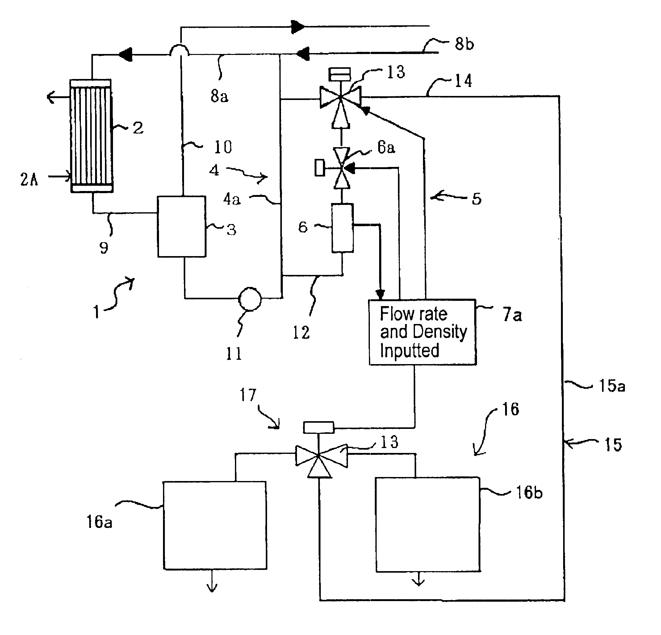
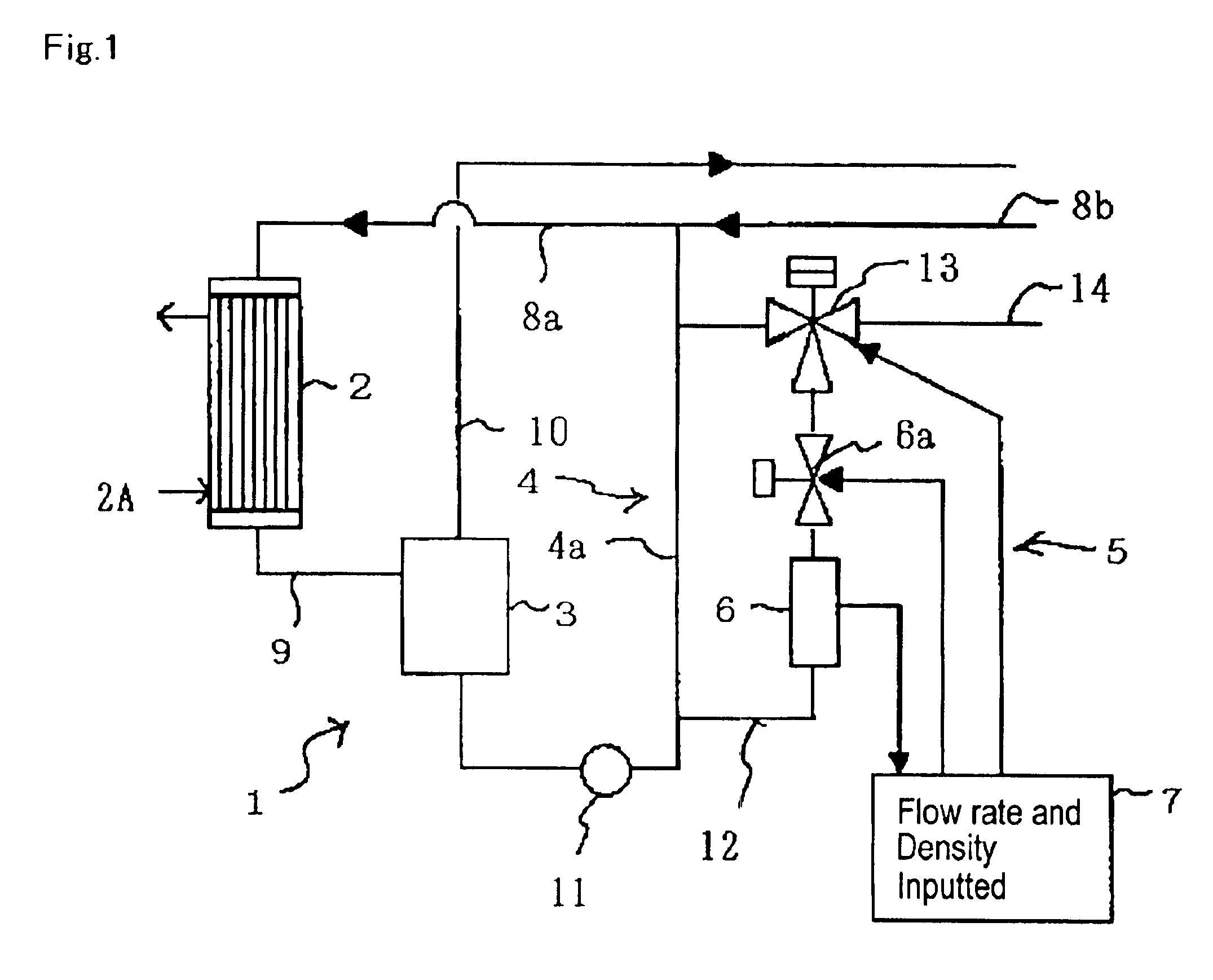
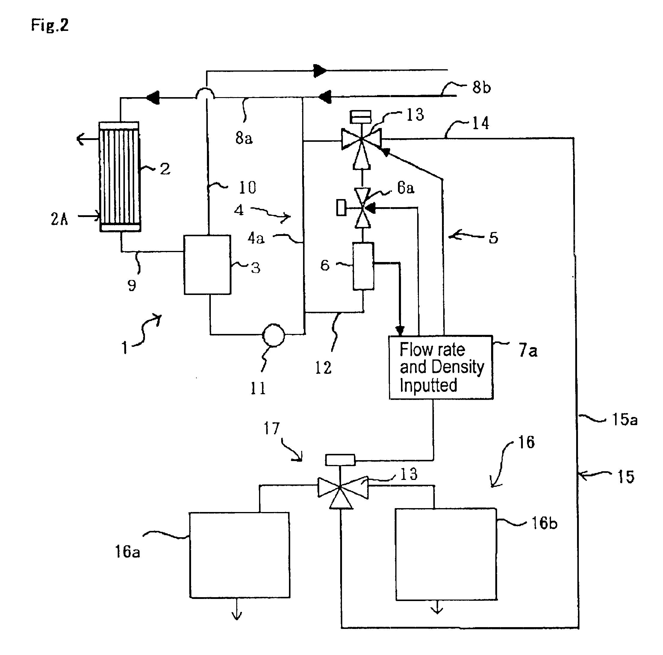
FIG. 1 is a schematic illustration of a concentrator that is an embodiment of this invention. As shown in FIG. 1, the concentrator (1) of this invention comprises a heater (2), a gas-liquid separator (3), a returning device (4), a liquid draw-out device (5), a concentration detector (6) and a controller (7).

Heater 2 is designed so as to heat a mixture of an extract or raffinate that is fed from a simulated moving bed chromatographic apparatus (not shown) and which may be called a feedstock hereinafter, with a liquid that is a concentrated liquid forcibly returned with returning device 4, to evaporate a portion of the mixture. Heating is carried out with heating means 2A that is capable of heating the mixture to above its boiling point under the operation pressure. When heater 2 is a forced-circulation falling film evaporator, a shell-and-tube exchanger of long-tube vertical type is employed for heating means 2A.

For this function, the top part of heater 2 is connected with feedstock ...


PUM

PropertyMeasurementUnit
Temperatureaaaaaaaaaa
Flow rateaaaaaaaaaa
Concentrationaaaaaaaaaa

Abstract

This invention provides a concentrator capable of drawing out a concentrate of a constant concentration. The concentrator includes a heater having a heating medium that has been heated to a temperature not less than the boiling point of a solution fed to the concentrator—whereby said heater heats the solution to evaporate the solvent to a vapor to make a mixture of the vapor and a liquid—and a gas-liquid separator for dividing the mixture into the liquid and the vapor. The concentrator provides for returning the liquid separated in the gas-liquid separator to the heater, for drawing out a portion of the liquid separated in the gas-liquid separator, for detecting the concentration of an intended component in the drawn out liquid, and for controlling the liquid draw-out so that when the concentration is above a predetermined threshold, liquid draw-out commences, and when the concentration is below the threshold, liquid draw-out stops.

Description

TECHNICAL FIELDThis invention relates to a concentrator, more particularly to a concentrator that is capable of concentrating a liquid to a desirable concentration.BACKGROUND ARTA forced-circulation falling film evaporator (often abbreviated to FFE), a continuous concentrator that has generally been used in various chemical processes, comprises a shell-and-tube exchanger, a gas-liquid separator, a returning line, a circulation pump, a draw-out line, a condenser, and a taking-out line. The shell-and-tube exchanger, which is a heater, heats a liquid with a heating medium that has been heated to a temperature above the boiling point of the liquid under the operation pressure. The heating changes the liquid to a mixture of vapor and liquid. The gas-liquid separator divides the mixture into a gas phase comprising the vapor and a liquid phase. The separated liquid together with the feedstock is returned to the shell-and-tube exchanger through the returning line. The circulation pump is pl...

Claims


Application Information

Patent Timeline
IPC IPC(8): B01D15/18B01D1/12B01D1/06B01D15/10B01D1/00B01D3/42C13F1/00C13B25/00C13B25/06
CPCB01D1/065B01D1/12B01D3/42B01D15/1821C13B30/002B01D3/4205Y10S203/09Y10S159/901
Inventor AKITA, KAZUYUKIMINODA, TOSHIHARU
Owner DAICEL CHEM IND LTD
Learn More