
Integrated circuit comprising a voltage generator and a circuit limiting the voltage supplied by the voltage generator

a voltage generator and integrated circuit technology, applied in the direction of electric variable regulation, emergency protective arrangements for limiting excess voltage/current, pulse automatic control, etc., can solve the problems of diode transistor breakdown voltage varies with time, cost price, diode transistor breakdown voltage, etc., to reduce the intensity of avalanche current and prevent the build-up of electric charges in the oxide of the pn junction

Active Publication Date: 2005-08-23
STMICROELECTRONICS SRL
View PDF8 Cites 7 Cited by
  • Summary
  • Abstract
  • Description
  • Claims
  • Application Information

AI Technical Summary

Benefits of technology

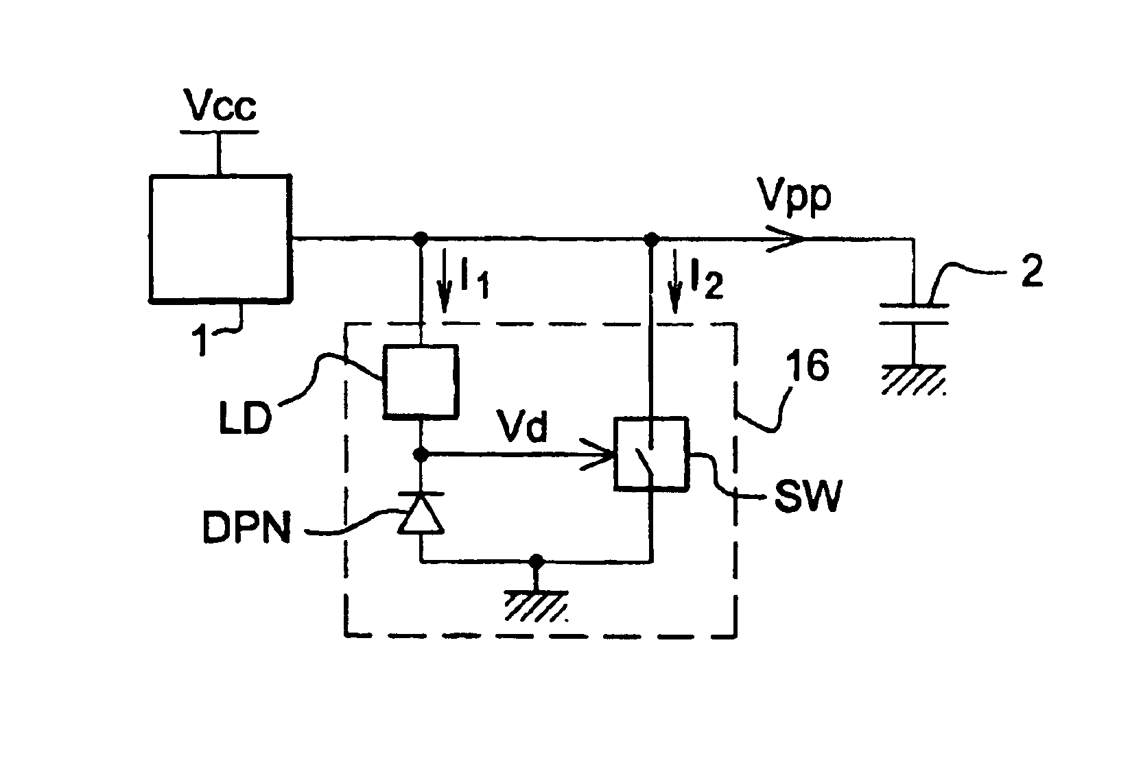
[0016]For that purpose, one idea of the present invention is to provide a switch in parallel with the PN junction, and to switch this switch into the on state when the PN junction becomes conductive so as to send the limiting current into the switch. For that purpose, the PN junction is linked to a load in series that reduces the intensity of the avalanche current and that forces almost all the limiting current to pass in the switch. Thus the build-up of electric charges in an oxide of the PN junction is prevented.

Problems solved by technology

Furthermore, the manufacture thereof requires specific doping steps that penalise the cost price.
Now, a diode transistor has the disadvantage that its breakdown voltage varies with time, since electric charges supplied by the avalanche current are trapped in the gate oxide of the diode transistor.
Certain manufacturers of integrated circuits adapt to this spurious effect but it results in a substantial imprecision as far as the voltage for triggering the PN junction limiting devices is concerned, which tends to increase with time.
Now, it is likely that this imprecision is the cause of the mediocre service life of certain memories in integrated circuits, the memory cells of which receive voltage Vpp peaks that are increasingly higher as the degradation of the breakdown voltage of the PN junction of their voltage-limiting devices increases.

Method used


Image

  • Integrated circuit comprising a voltage generator and a circuit limiting the voltage supplied by the voltage generator
  • Integrated circuit comprising a voltage generator and a circuit limiting the voltage supplied by the voltage generator
  • Integrated circuit comprising a voltage generator and a circuit limiting the voltage supplied by the voltage generator

Examples


Embodiment Construction

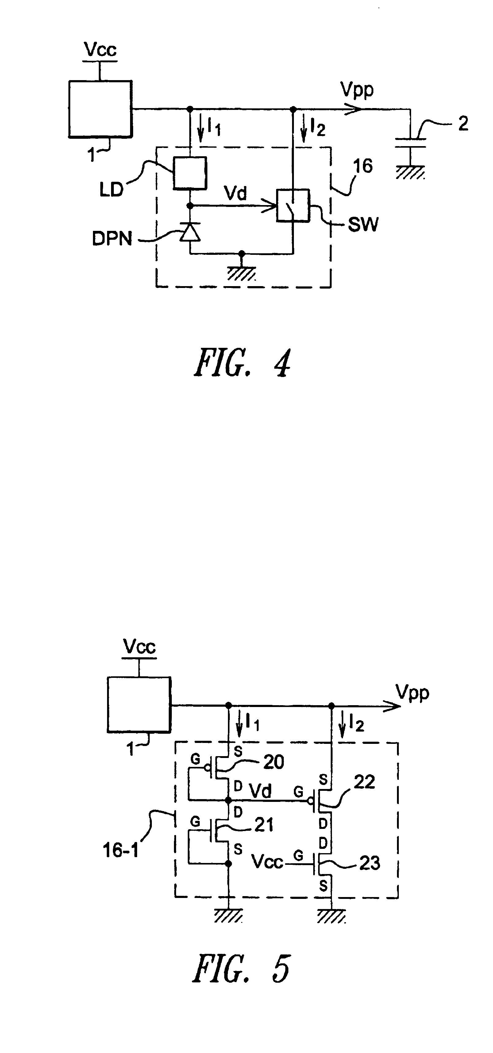
[0035]Referring initially to FIG. 4, show therein is a schematic diagram of a voltage-limiting device 16 according to one embodiment of the present invention. The voltage-limiting device 16 is arranged in an integrated circuit, between the output of a booster circuit 1 and the ground. The booster circuit 1 is for example a charge pump powered by a voltage Vcc, supplying a voltage Vpp. The voltage Vpp is applied to a load 2, here a capacitive load representing as an example gate capacitances of memory cells to be erased or to be programmed.

[0036]The voltage-limiting device 16 comprises a trigger stage comprising a PN junction in series with a load LD with high series resistance. The PN junction is arranged in the reverse direction and is represented here in the shape of a diode DPN the anode of which is grounded (the diode being reverse arranged) and the cathode of which is linked to the output of the booster circuit 1 through the load LD.

[0037]The voltage-limiting device 16 also com...


PUM


Abstract

An integrated circuit having a voltage generator supplying a determined voltage, a voltage-limiting circuit arranged at the output of the voltage generator, the voltage-limiting circuit having at least one PN junction formed by a diode-arranged MOS transistor, the PN junction having a breakdown voltage defining a threshold for triggering the voltage-limiting circuit as from which the PN junction is on by avalanche effect, at least one load in series with the PN junction for limiting an avalanche current passing through the PN junction when the PN junction is on, and at least one switch in parallel with the PN junction and the load, the switch arranged in the open state when the PN junction is off and to be in the closed state when the PN junction is on.

Description

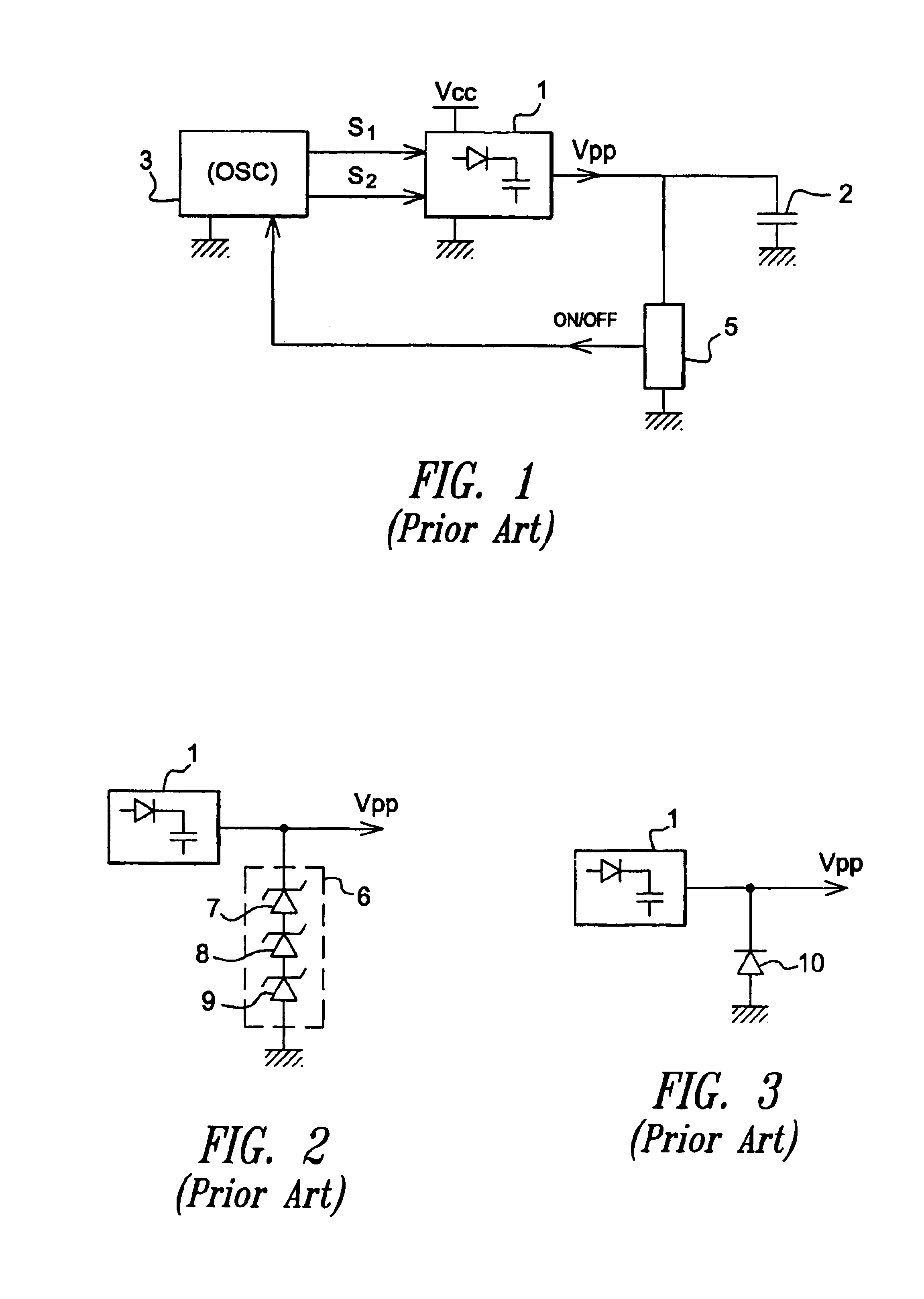
BACKGROUND OF THE INVENTION[0001]1. Field of the Invention[0002]The present invention relates to an integrated circuit comprising a voltage generator and a circuit limiting the voltage supplied by the voltage generator.[0003]2. Description of the Related Art[0004]Booster circuits such as charge pumps allow an electric voltage higher than a determined supply voltage to be produced. In the field of integrated circuits, charge pumps for example are used to produce the high voltage Vpp for erasing and programming the floating-gate transistors of the electrically erasable and programmable memories (EEPROM, FLASH, FLASH-EEPROM . . . ).[0005]FIG. 1 schematically represents a charge pump 1 supplying a boosted voltage Vpp to a load 2, here a capacitive load. This capacitive load is for example equal to the sum of the spurious gate capacitances of a plurality of floating-gate transistors to be erased or to be programmed simultaneously. The charge pump 1 is driven by clock signals S1, S2 in op...

Claims


Application Information

Patent Timeline
IPC IPC(8): H02H9/04
CPCH02H9/046
Inventor DEVIN, JEAN
Owner STMICROELECTRONICS SRL
Learn More