
Control method and system for motor

a control method and motor technology, applied in the direction of motor/generator/converter stopper, dynamo-electric converter control, instruments, etc., can solve the problem of current phase-lag, and achieve the effect of high accuracy, low cost and fast respons

Inactive Publication Date: 2005-08-23
NAT KAOHSIUNG UNIV OF SCI & TECH
View PDF6 Cites 12 Cited by
  • Summary
  • Abstract
  • Description
  • Claims
  • Application Information

AI Technical Summary

Benefits of technology

The solution effectively eliminates phase-lag issues, achieves high accuracy, fast response, and robustness, with economic advantages such as low cost, and maintains constant switching frequency, even with varying leakage inductance values within ±50% error.

Problems solved by technology

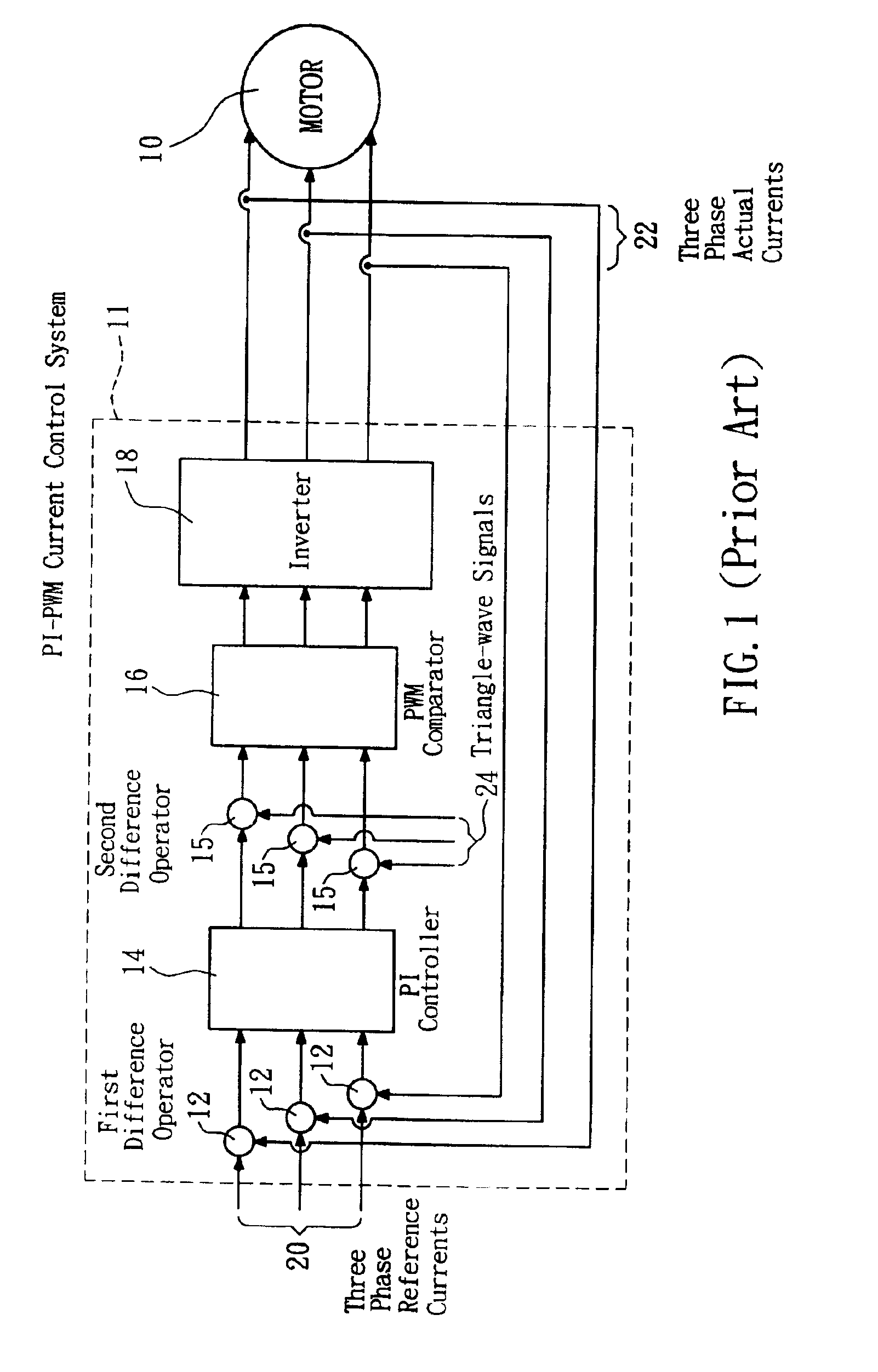
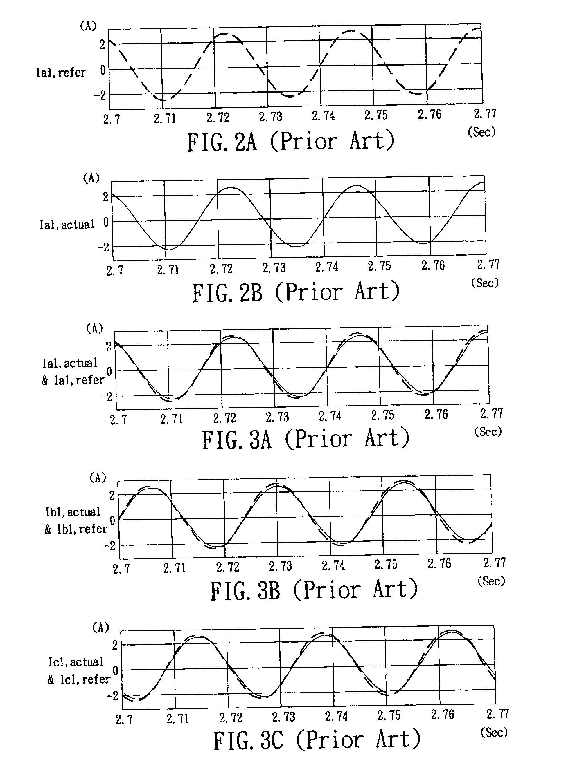
However, the conventional PI-PWM current control system 11 has the current phase-lag problem.

Method used


Image

  • Control method and system for motor
  • Control method and system for motor
  • Control method and system for motor

Examples


Embodiment Construction

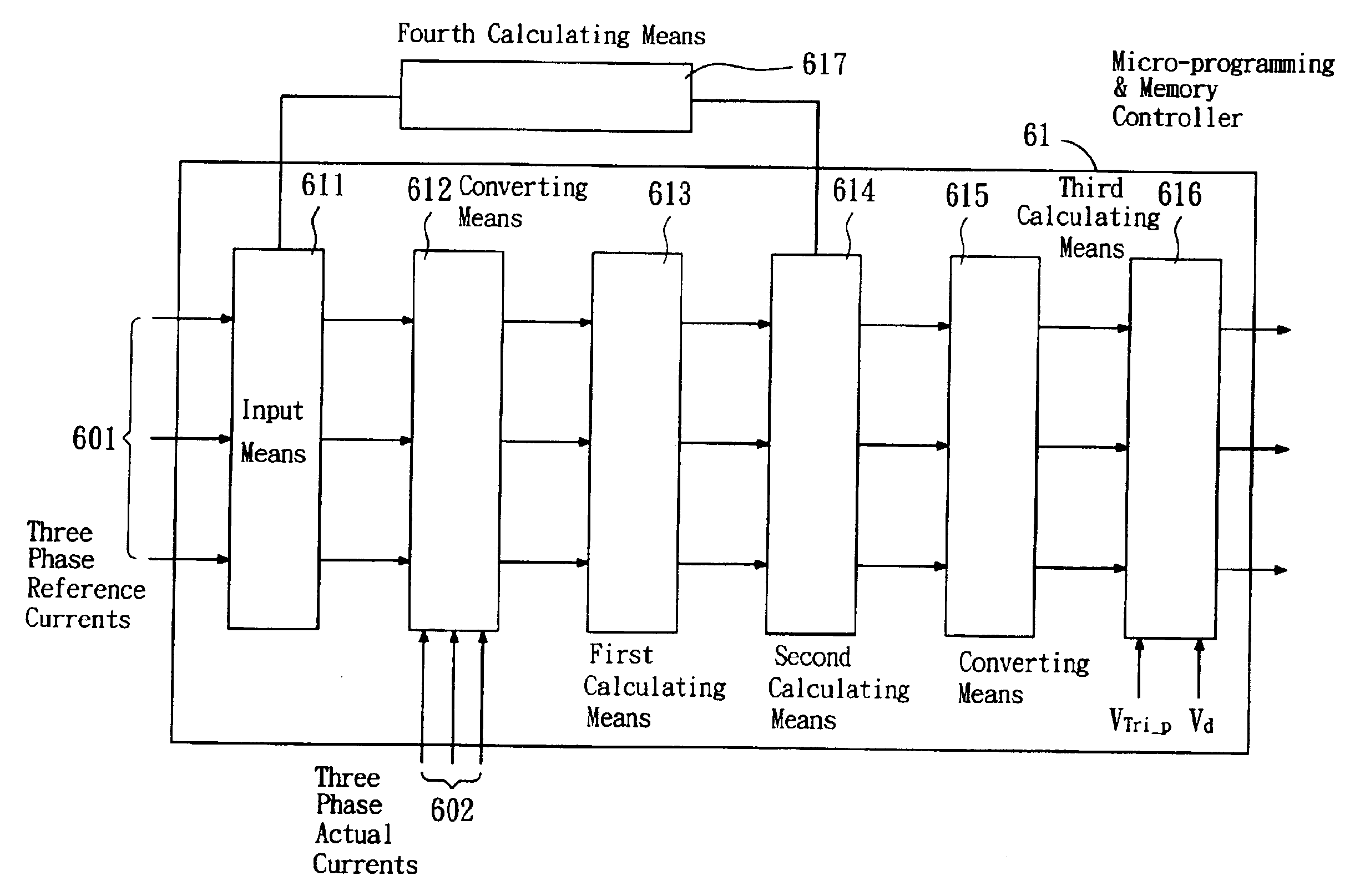
[0032]The control method of the invention can be utilized to control an AC motor, more particularly to control an induction motor so that three phase actual currents are equal to three phase reference currents. In the embodiment, the induction motor is taken as an example to describe the operation of the control method and system of the invention. However, the control method and system of the invention are not limited to control the induction motor, the other AC motor and DC motor can be controlled by the control method and system of the invention.

[0033]Firstly, the induction motor dynamic equations on the synchronous rotating d-q frame are shown as follows Equation (1). ⅆ ⅆt[ ⁢idsiqsλdrλqr]= [-(rsLσ+rr′·LM′2Lσ·Lrr′2)ωerr′·LMLσ·Lrr′2ωr⁢LMLσ⁢Lrr′-ωe-(rsLσ+rr′·LM2Lσ·Lrr′2)-ωr⁢LMLσ·Lrr′rr′·LMLσ⁢Lrr′2rr′⁢LMLrr′0-rr′Lrr′(ωe-ωr)0rr′⁢LMLrr′-(ωe-ωr)-rr′Lrr′]· [idsiqsλdrλqr]+[1Lσ001Lσ0000]·[VdsVqs](1)

[0034]wherein Lσ is defined as a leakage induction. Lσ=(1-LM2Lss⁢Lrr)⁢Lss=Lss⁢Lrr-LM2Lrr=lea...


PUM


Abstract

The invention relates to a control method and a control system for a motor. The control method and the control system of the invention transfer the motor dynamic equations of the synchronous d-q frame into a motor parameter (for example, the leakage inductance) and the equivalent counter electromotive force. Then the required control signals for the motor current control can be obtained. The control method of the invention not only preserves the merit of constant switching frequency of the convention PI-PWM control system, but also can eliminate the motor current phase-lag problem of the invention PI-PWM control system. Also, the control method of the invention will have the following characteristics and economic advantages such as high accuracy, fast response, low cost and robustness, etc.

Description

BACKGROUND OF THE INVENTION[0001]1. Field of the Invention[0002]The present invention relates to a control method and system for a motor, more particularly, to a control method and system using a micro-programming & memory controller for a motor.[0003]2. Description of the Related Art[0004]FIG. 1 shows a conventional PI-PWM (Proportion Integration-Pulse Width Modulation) current control system 11 for a motor 10. The conventional PI-PWM current control system 11 comprises: a first difference operator 12, a PI controller 14, a second difference operator 15, a PWM comparator 16 and an inverter 18. The control system 11 receives three phase reference currents 20 to the first difference operator 12, and detects three phase actual currents 22 from a motor 10. The first difference operator 12 calculates three phase difference currents between the three phase reference currents 20 and three phase actual currents 22.[0005]The three phase difference currents are amplified by the PI controller...

Claims


Application Information

Patent Timeline
Patent Type & Authority Patents(United States)
IPC IPC(8): H02M3/335
CPCH02P21/0032H02P21/0035H02P21/34H02P21/22
Inventor HSU, CHIN-YUAN
Owner NAT KAOHSIUNG UNIV OF SCI & TECH
Learn More