
Method of making an electrostatic actuator

a technology of electrostatic actuators and actuators, applied in the field of electrostatic actuators, can solve the problems of inter-metallic diffusion, limit the long-term reliability and reproducibility of these devices, and cannot solve the problem completely, so as to achieve the effect of reducing stress concentration

Inactive Publication Date: 2005-08-23
SUPERCONDUCTOR TECHNOLOGIES INC
View PDF13 Cites 54 Cited by
  • Summary
  • Abstract
  • Description
  • Claims
  • Application Information

AI Technical Summary

Benefits of technology

[0013]In another embodiment, the metal layer is deposited in a two step deposition process of a soft metal deposition followed by a hard metal deposition, where the deposited hard metal exhibits higher intrinsic stress than the soft metal. The soft and hard metal are both made of the same metal, e.g., gold, characterized by different crystal grain sizes. In one embodiment, the electroplating bath used to deposit the hard metal contains dopants to enhance the intrinsic stress in the hard metal.
[0014]In another embodiment of the invention, the metal layer is deposited using evaporation, such as electron beam evaporation. In this embodiment, the stress gradient is induced in the metal layer by varying the deposition rate during deposition of the metal layer. In one embodiment, an initial upward curvature of the beam is obtained by increasing the deposition rate during deposition of the metal layer.
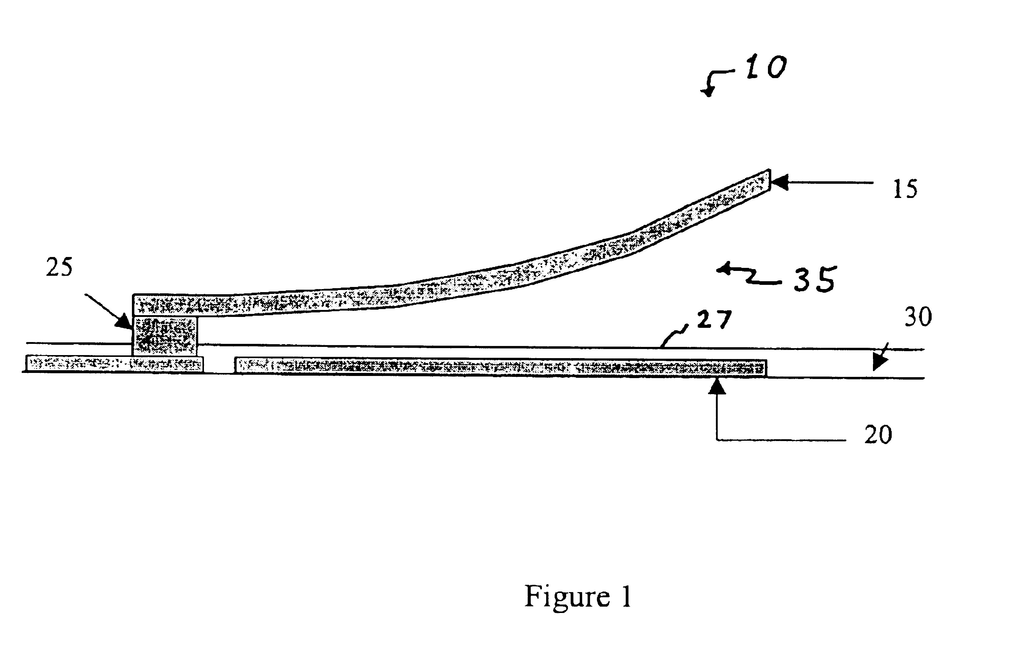
[0019]In another embodiment of the invention, the front edge of the beam is curved to alleviate stress concentration due to sharp corners.

Problems solved by technology

Although the usefulness of conventional electrostatically actuated devices has been demonstrated, there are a number of problems with these devices stemming from the use of the bimetallic beam.
The mechanical properties of the bimetallic beam have been shown to change with time due to inter-metallic diffusion between the two metals and recrystallization, thereby limiting the long term reliability and reproducibility of these devices.
The introduction of a diffusion barrier layer between the two metal layers can help reduce inter-metallic diffusion but can not solve it completely.
Furthermore, the operation of these devices requires precise temperature control because any variation in temperature leads to a change in the deflection of the bimetallic beam, which in turn changes the capacitance of these devices.
However, the requirement that the two metals have different CTEs in order to achieve a desired initial curvature restricts the types of metal that are available to construct the bimetallic beam.
As a result, the mechanical and electrical properties of the cantilever beam are compromised.

Method used


Image

  • Method of making an electrostatic actuator
  • Method of making an electrostatic actuator
  • Method of making an electrostatic actuator

Examples


Embodiment Construction

[0034]The present invention is believed to be applicable to a variety of electrostatic actuators requiring electrostatically actuated beams. The present invention is particularly applicable to electrostatically actuated variable capacitors. While the present invention is not so limited, an appreciation of the present invention is best presented by way of a particular example application, in this instance, in the context of such electrostatically actuated variable capacitors.

[0035]Turning to the drawings, FIG. 1 shows a cross section of an electrostatically actuated capacitor 10 according to an embodiment of the invention. The capacitor 10 comprises a base substrate 30, a bottom electrode 20 on the substrate 30 and a curved cantilever beam 15, which act as a top movable electrode of the capacitor 10. The cantilever beam 15 according to the invention comprises a metal layer with an intrinsic stress gradient induced therein. The metal layer is substantially made of a single metal. The ...


PUM


Abstract

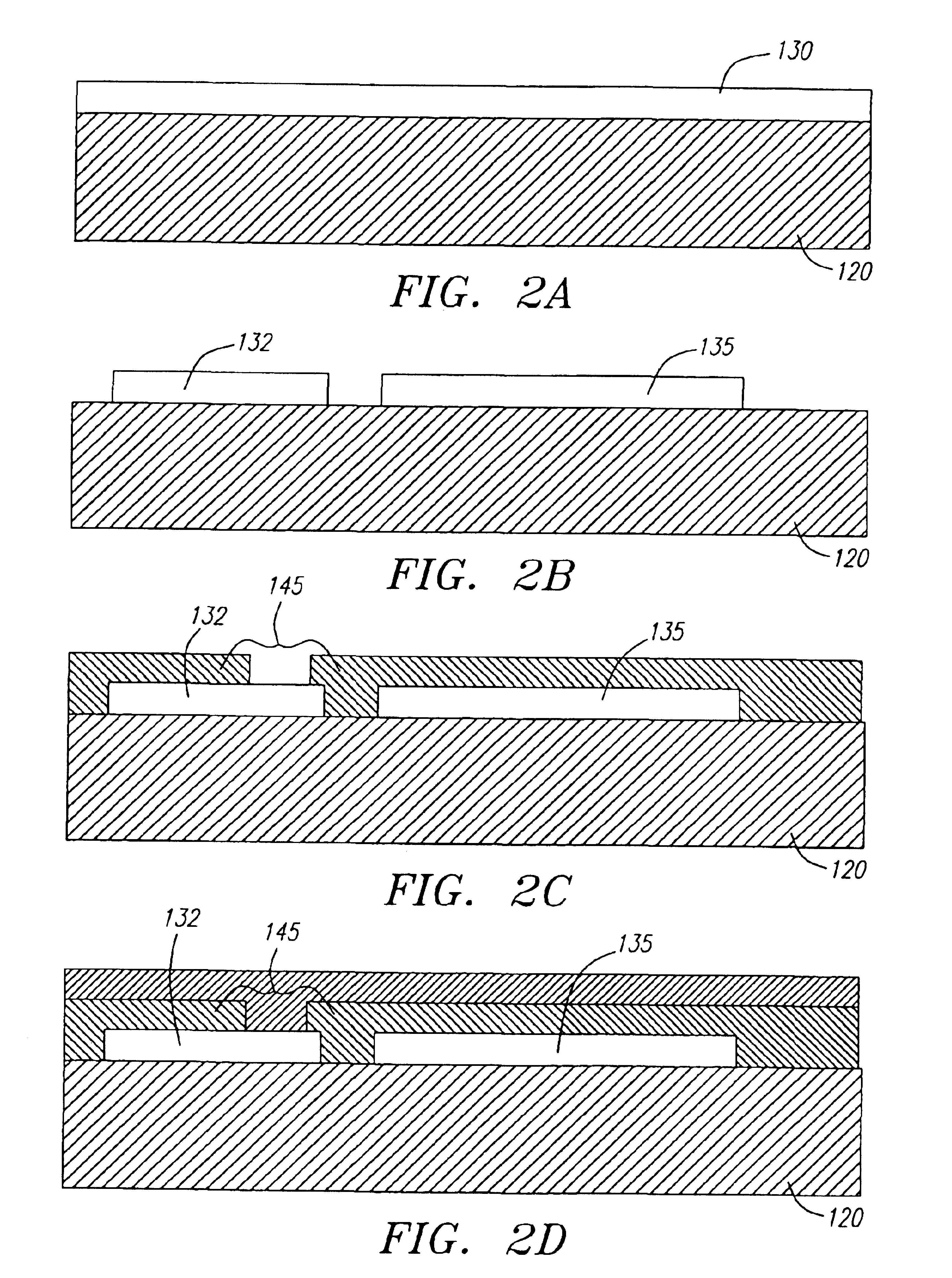
A method of fabricating an electrostatic actuator with an intrinsic stress gradient is provided. An electrode is formed on a substrate and a support layer is formed over the electrode. A metal layer is deposited onto the support layer via a deposition process. Deposition process conditions are varied in order to induce a stress gradient into the metal layer. The intrinsic stress in the metal layer increases in the direction from the bottom to the top of the metal layer. The support layer under the electrode is removed to release the electrostatic actuator.

Description

RELATED APPLICATION[0001]This Application is a continuation of U.S. application Ser. No. 09 / 944,867, filed Aug. 31, 2001, issued on Sep. 23, 2003 as U.S. Pat. No. 6,625,004, incorporated herein by reference as if set forth fully hereinU.S. GOVERNMENT LICENSE RIGHTS[0002]The U.S. Government has a paid-up license in this invention and the right in limited circumstances to require the patent owner to license others on reasonable terms as provided for by the terms of DARPA contract MDA972-00-C-0010.TECHNICAL FIELD[0003]The invention relates to electrostatic actuators, and more particularly, to electrostatic actuators with intrinsic stress gradient.BACKGROUND OF THE INVENTION[0004]Electrostatically actuated beams are one of the fundamental building blocks in Micro-Electro-Mechanical System (MEMS) devices, and find applications in a variety of fields, such as communications, sensing, optics, micro-fluidics, and measurement of materials properties. In the field of communications, electrost...

Claims


Application Information

Patent Timeline
IPC IPC(8): H01G5/00H01G5/18H01H59/00
CPCB82Y30/00H01G5/18H01H59/0009H01H2059/0081
Inventor MUSOLF, JURGENKOHL, PAUL
Owner SUPERCONDUCTOR TECHNOLOGIES INC
Learn More