
Closed loop direct expansion heating and cooling system with auxiliary refrigerant pump

a technology of direct expansion and refrigerant pump, which is applied in the direction of heat pumps, domestic cooling apparatus, lighting and heating apparatus, etc., can solve the problems of reducing affecting the operational efficiency of the system, and affecting the operation efficiency of the system. , to achieve the effect of inhibiting was

Inactive Publication Date: 2005-08-23
EARTH TO AIR SYST
View PDF12 Cites 52 Cited by
  • Summary
  • Abstract
  • Description
  • Claims
  • Application Information

AI Technical Summary

Benefits of technology

[0008]The liquid refrigerant fluid pump will be sized to offset the head pressure of the liquid state refrigerant in the liquid line, depending on the volume, weight, depth or height, of fluid in the liquid line, as well as taking other factors into account, such as the system operating pressures, the refrigerant transport tubing's interior wall resistance, the overall refrigerant fluid volume, and the like, which factors and calculations are readily understood by those in the field. This will enable the compressor to operate at its maximum design efficiency as a compressor, and will further enable direct-expansion, refrigerant-based, geothermal heating and cooling systems, whether operating in a single heating or cooling mode or in a reverse-cycle mode, to efficiently operate with the in-ground heat exchange lines installed at any depth, or at any elevation, or at any distance, desired. Liquid pumps operate very efficiently with minimal power requirements. Refrigerant compressors operate very efficiently as compressors when they are not required to additionally provide pumping power, for which pumping purposes they were not primarily designed. Consequently, the invention enables maximum efficiencies to be achieved when significant elevation differentials are desirable between the compressor and the condenser, such as when the in-ground heat exchange tubing is installed in a deep well direct expansion geothermal system operating in a cooling mode.
[0010]Another advantage of utilizing a fluid pump in a direct expansion system would be to solve the common low-pressure start-up problem when the system is operating in the cooling mode. Since refrigerant fluid naturally migrates to the coolest point in the system, at the beginning of the cooling season, when the ground is operating as the condenser in a direct expansion geothermal heat pump system, the ground surrounding the condensing lines has supplied heat throughout the winter and is usually the coldest point. As a result, when the system has satisfied the interior air temperature requirements and shuts off, a significant portion of the refrigerant fluid migrates to the cold ground condensing lines and remains there in a liquid state. Consequently, the refrigerant in a vapor state is depleted, often causing the compressor to automatically shut down via its own internal low-pressure safety cut-off design. To overcome this problem, various geothermal direct expansion system designs, such as William E. Dressler U.S. Pat. No. 5,461,876 incorporate a re-programming of the compressor to continue to operate, or to continue to periodically repeat the start-up mode until enough refrigerant is moved into the evaporator to commence normal system operation. This re-programming of the compressor reduces the compressor life and consumes large amounts of energy, thereby reducing overall system efficiencies. By programming the fluid pump to start prior to the compressor, as is readily understood by those skilled in the trade, so as to equalize or to approximately equalize refrigerant pressures on both sides of the compressor unit, the necessity to re-program the compressor to continuously repeat start-up attempts under low pressure conditions is eliminated.
[0015]Absent a readily available submersible liquid refrigerant pump, an available Side Channel Pump, with an optional by-pass valve to prevent any vapor lock potential and to initiate self-priming, or the like, can be utilized for effective system operation. Although not typically reversible, Side Channel Pumps, such as those manufactured by Corkin, Inc., can be placed at an accessible above-ground location in the liquid line between the two expansion valves. Reverse direction refrigerant fluid flow through a Side Channel Pump is easily accomplished by means of one directional piping and valve by-passes, just as utilized for the compressor, as is well known and understood by those in the trade. Again, rather than require a variable speed Side Channel Pump for reversible system operation or other changing conditions, more than one such pump, of respective varying powers, can be placed in respective divided segments of the liquid refrigerant line, with one or more such pumps programmed to operate depending upon system requirements.
[0016]An alternative to utilizing a Side Channel Pump, or the like, would be to utilize a readily available, but oversized, scroll compressor, or the like, in its place, such as those scroll compressors manufactured by Scroll Technologies, of One Scroll Drive, Arkadelphia, Ark. 71923. Scroll compressors, well known to those skilled in the field, can effectively pump either refrigerant liquid or vapor. By over-sizing a standard scroll compressor so that the intake is expanded in size, but so that the discharge capacity and rate, after having calculated and added appropriate capacity for fluid head pressure and line resistance factors and the like, is equal or approximately equivalent to the intake design rate of the system's primary compressor unit, with the system's primary compressor unit's intake rate calculated absent any system liquid head or line resistance issues, and the like, taken into account, there will be either no or minimal compression work load expended by the scroll pumping unit, and the over-sized scroll compressor will, as a result, efficiently utilize its energy solely in a pumping capacity.
[0017]In another alternative, the scroll compressor, designed to compress a refrigerant vapor, can be easily modified by the factory to a non-compression scroll design, as would be readily understood by those in the trade, so as to avoid the necessity to oversize the scroll unit when solely utilized in a pumping capacity. The same applications and the same factory modification, as described for a scroll compressor unit, can be applied to a screw compressor unit, such as those manufactured by York International, of 631 South Richland Avenue, York, Pa. 17403, or to any other appropriately designed compressor unit capable of pumping both vapor and liquid state refrigerant.

Problems solved by technology

Since compressors are primarily designed to act as compressors, even when there is a modest elevation differential, such as 10 to 25 feet, between the compressor and the condenser, such that a refrigerant liquid elevation load is placed on the compressor which is now required to perform increased pumping work, system operational efficiencies are noticeably impaired.
Beyond 50 to 100 feet, system operational efficiencies are materially impaired.
This is due to the increasing head pressure of the refrigerant liquid on its way up from an elevation materially lower than the compressor, as compressors are not designed to operate as liquid elevation pumps.
Since most refrigerant heat pump systems do not operate under constant conditions, most utilize self-adjusting expansion valves in both the heating and the cooling modes.
These valves operate at their peak efficiencies when they are close, generally within about two feet, to the heat exchange means operating as the evaporator, and the greater the distance, the lower their operational efficiency as these valves become more prone to hunting rather than to maintaining an optimum setting.

Method used


Image

  • Closed loop direct expansion heating and cooling system with auxiliary refrigerant pump
  • Closed loop direct expansion heating and cooling system with auxiliary refrigerant pump
  • Closed loop direct expansion heating and cooling system with auxiliary refrigerant pump

Examples


Embodiment Construction

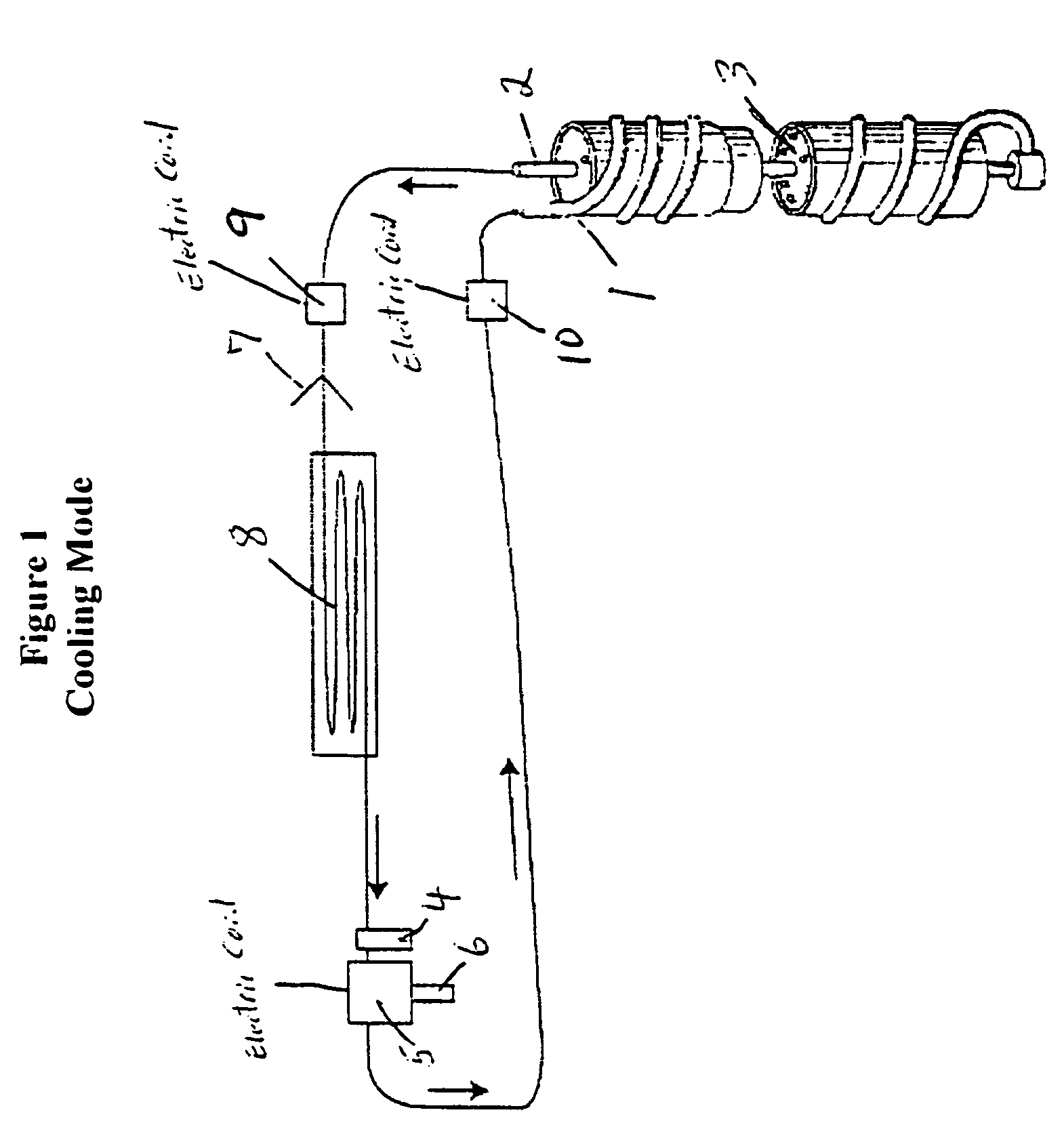
[0023]FIG. 1 is a schematic view of an example direct expansion cooling system with a deep in-ground heat exchange supply line 1 and a correspondingly deep in-ground heat exchange insulated return line 2, with the return line surrounded by insulation 3, as more fully described in U.S. Pat. No. 5,623,986 to Wiggs. Additionally shown is an accumulator 4, a standard compressor unit 5 with an attached standard oil separator 6, a standard expansion valve 7 in close proximity to a particular system design standard interior air heat exchanger 8, with an auxiliary refrigerant vapor pump 10 connected to the in-ground heat exchanger supply line 1, and with an auxiliary refrigerant liquid pump 9 connected to the in-ground heat exchanger return line 2.

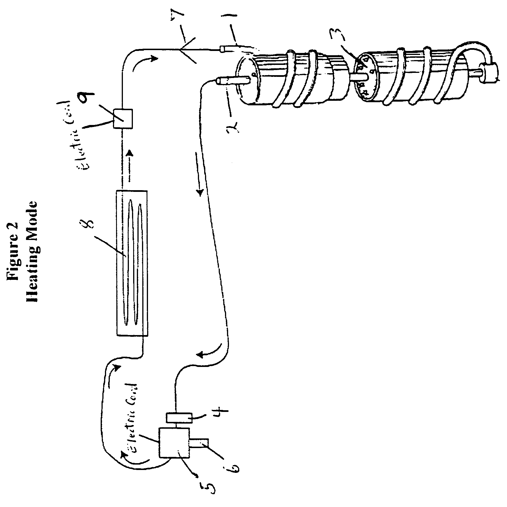
[0024]FIG. 2 is a schematic view of an example direct expansion heating system with a deep in-ground heat exchange supply line 1 and a correspondingly deep in-ground heat exchange insulated return line 2, with the return line surrounded by insulat...


PUM


Abstract

A direct expansion refrigerant-based heating and cooling system which includes a refrigerant pumping devise calibrated to ease or eliminate the pumping requirements placed upon the system's compressor unit when one or both of significant system height differentials between the compressor unit and the condensing unit are present and significant system refrigerant fluid transport line distances are present, or are desirable, such as in a deep well direct expansion system application.

Description

BACKGROUND OF THE INVENTION[0001]The invention relates to the field of closed-loop, refrigerant-based, direct expansion, heating and cooling systems which encounter one or more of significant system component height differentials, particularly significant compressor and condenser height differentials, and significant system refrigerant fluid transport line distances. The invention is of particular advantage in direct expansion heating and cooling systems, wherein a refrigerant fluid, such as R-22, or the like, is circulated by a compressor through heat conductive tubing, typically copper tubing, located below ground, to acquire heat from the ground in the winter and to reject heat into the ground in the summer. This direct expansion system in-ground heat exchange system typically eliminates the need for the outdoor air heat exchange unit in a conventional air-source heat pump system, and eliminates the need for an open or a closed loop of circulating water in a conventional water so...

Claims


Application Information

Patent Timeline
IPC IPC(8): F25B13/00F25B30/06F25B30/00F24J3/08
CPCF24J3/083F25B13/00F25B30/06F25B2313/0271F25B2313/02791F25B2600/0253Y02B30/741Y02E10/125F24T10/15Y02B30/70Y02E10/10
Inventor WIGGS, B. RYLAND
Owner EARTH TO AIR SYST
Learn More