
Square cell container and method of manufacturing the cell container

Inactive Publication Date: 2005-08-16
PANASONIC CORP +1
View PDF13 Cites 6 Cited by
  • Summary
  • Abstract
  • Description
  • Claims
  • Application Information

AI Technical Summary

Benefits of technology

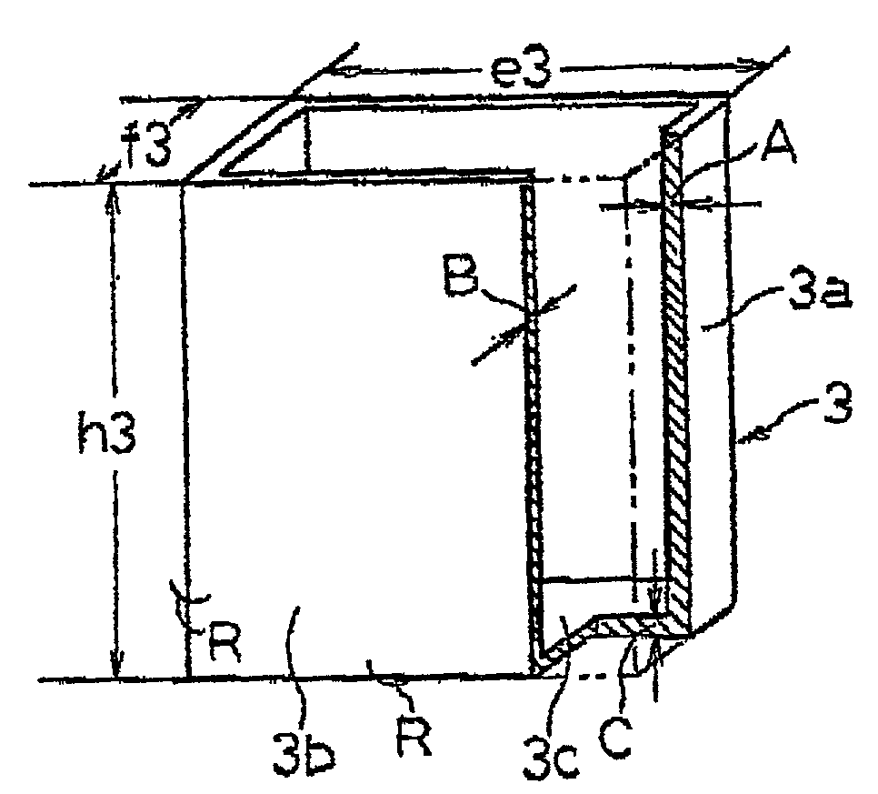
[0012]A prismatic battery employing such a prismatic battery case has the following advantage. In the battery case with a substantially rectangular cross section, its shorter-side plate has a relatively large thickness. Thus, even when the battery is activated and the internal pressure is increased, the shorter-side plate, just like a supports prevents the battery from becoming distended like a barrel to approach a configuratively stable cylindrical shape. In the prismatic battery case, occurrence of leakage of electrolyte and damage and malfunction in the appliance is therefore prevented, and thus its use realizes a highly reliable prismatic battery. Moreover, a longer-side plate, which is larger in area than the shorter-side plate, is made relatively thin and the content volume of the prismatic battery case is accordingly increased. This allows the battery case to contain a larger amount of battery active material, so that the volume energy density is increased. Further, in the battery case cracking and rupture encountered by the shorter-side plate during DI processing is avoided by making the thickness of the shorter-side plate relatively large. This means that a prismatic battery case is easily manufactured by the DI method having various advantages.
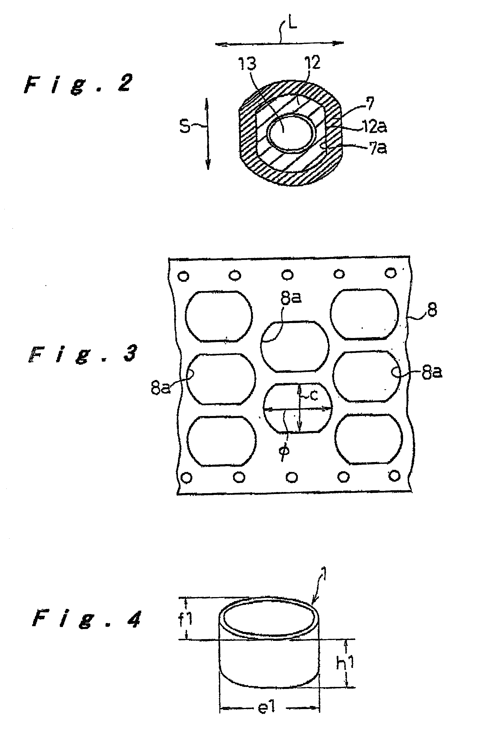
[0027]Conventionally, a first intermediate cup element having a nearly circular, substantially elliptic cross section is formed by punching it out of a battery case material into disc-like shape. In this case, however, a finished prismatic battery case obtained through the final step has a large lug protruding upwardly from its shorter-side plate. To cut this lug, an additional operation is required. By contrast, if the cup element is formed by punching it out of a battery case material into an oval shape so that the finished prismatic battery case no longer has a lug, protruding upwardly from the shorter-side plate, to be cut off after completion of the prismatic battery, the punched holes remaining in the battery case material are arranged as tightly as possible compared to conventional cases. This helps reduce material losses.

Problems solved by technology

However, in a prismatic battery case manufacturing method based on the transfer drawing, deep drawing and stamping need to be repeated over a dozen or so times. This leads to poor productivity (for example, 20 pieces of articles per minute).
Thus, a prismatic battery case realized by the transfer drawing suffers from lower strength and thus fails to provide a desired pressure withstanding strength when operated as a battery system.
This might cause leakage of electrolyte and damage to the appliance.
In this case, however, the following problem arises.
Accordingly, the material flows unevenly during the processing and is thus processed unstably, with the result that cracking, rupture, or distortion tends to occur particularly in the shorter-side plate of the battery case which is smaller in area.
For this reason, it has conventionally been impossible to fabricate a prismatic battery case by the DI method.
In either case, however, the productivity is extremely unfavorable, and what is worse, it is impossible to form a battery case having a strength high enough to prevent deformation due to increased battery internal pressure without sacrificing its slimness and lightness.
This makes it impossible to attain satisfactory volume energy density and weight energy density.
Moreover, the method requires time-consuming operations including accurate positioning of the rectangular barrel and the bottom plate and laser welding process.
This makes it impossible to attain improved productivity.
Further, a prismatic battery case realized by the method fails to satisfy two mutually contradictory requirements, namely, offering higher energy density attained as a result of reduction in thickness and weight and offering pressure withstanding strength high enough to prevent deformation due to increased battery internal pressure.

Method used


Image

  • Square cell container and method of manufacturing the cell container
  • Square cell container and method of manufacturing the cell container
  • Square cell container and method of manufacturing the cell container

Examples


Embodiment Construction

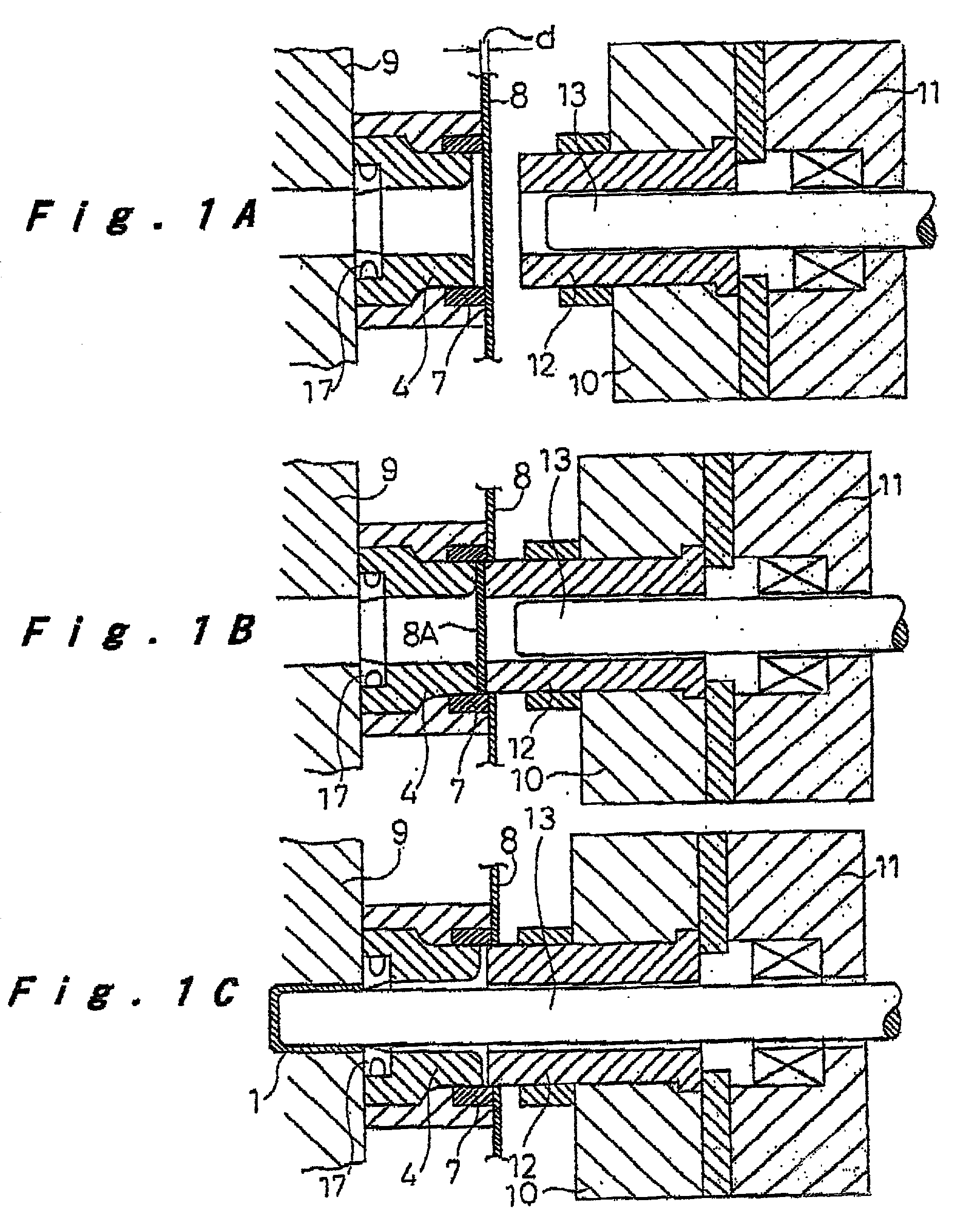
[0041]Hereinafter, preferred embodiments of the present invention will be described with reference to the accompanying drawings. In a prismatic battery case manufacturing method according to one embodiment, at a first process step shown in FIG. 1 representing a schematic horizontal sectional view, a battery case material 8 is subjected to punching and deep drawing so as to a first intermediate cup element 1 having a nearly circular, substantially elliptic cross section as shown in FIG. 4. At a second process step shown in FIGS. 5 and 6, the first intermediate cup element 1 is subjected to four steps of redrawing processing successively so as to form a second intermediate cup element 2 with a substantially elliptic cross section having a smaller minor-axis-diameter to major-axis-diameter ratio as shown in FIG. 7. Subsequently, at a third process step shown in FIG. 8 representing a schematic horizontal sectional view, the second intermediate cup element 2 is subjected to DI processing...


PUM

PropertyMeasurementUnit
Fractionaaaaaaaaaa
Shapeaaaaaaaaaa

Abstract

A prismatic battery case (3) has a configuration wherein a rectangular shorter-side plate (3a) has a thickness (A) larger than a thickness (B) of a longer-side plate (3b). When the prismatic battery case (3) is manufactured, a battery case material (8) punched into a predetermined shape undergoes deep drawing to form a first intermediate cup element (1) having a substantially elliptic cross section; the first intermediate cup element (1) undergoes redrawing successively in a plural stages to form a second intermediate cup element (2) having a substantially elliptic cross section which is smaller in minor-axis-diameter to major-axis-diameter ratio; and the second intermediate cup element (2) undergoes DI processing to form the prismatic battery case (3) having a substantially rectangular cross section wherein the thickness (A) of the shorter-side plate (3a) is made larger than the thickness (B) of the longer-side plate (3b).

Description

TECHNICAL FIELD[0001]The present invention relates to a prismatic battery case for use in various prismatic batteries such as a lithium-ion rechargeable battery, and to a method for manufacturing the prismatic battery case by DI (Drawing and Ironing) processing method (i.e. by successively performing both of drawing and ironing processing at a time).BACKGROUND ART[0002]In recent years, electronics technology advances have allowed higher performance, miniaturization, and reduction in weight and power consumption in electronic equipment. Consequently, various household portable appliances have been developed and put into practical use and their marketplace has been rapidly expanded. Representative examples thereof include a cam-corder, a notebook-type personal computer, and a portable telephone. This trend has created an increasing demand for further miniaturization and weight reduction as well as longer time duration in such appliances. To comply with such requirements, a lithium rec...

Claims


Application Information

Patent Timeline
IPC IPC(8): H01M2/02H01M50/119H01M50/124H01M50/133H01M50/134
CPCH01M2/023H01M2/0275H01M2/027H01M2/0217Y10T29/53135Y10T29/49108B21D22/28Y02E60/10H01M50/103H01M50/56H01M50/545Y02P70/50H01M50/133H01M50/124H01M50/119H01M50/134
Inventor MORI, KATSUHIKOKITAOKA, SUSUMUYAMASHITA, SHOJITANAKA, SHIGEKAZU
Owner PANASONIC CORP
Learn More