Waste stream digestion method
a technology of waste stream and digestion method, which is applied in the direction of water/sewage treatment by oxidation, sustainable biological treatment, biological water/sewage treatment, etc. it can solve the problems of slow anaerobic process, large amount of energy, and rapid solids so as to eliminate the effect of solid waste build-up in the lagoon, less energy, and large circulation
- Summary
- Abstract
- Description
- Claims
- Application Information
AI Technical Summary
Benefits of technology
Problems solved by technology
Method used
Image

Examples
embodiment 100
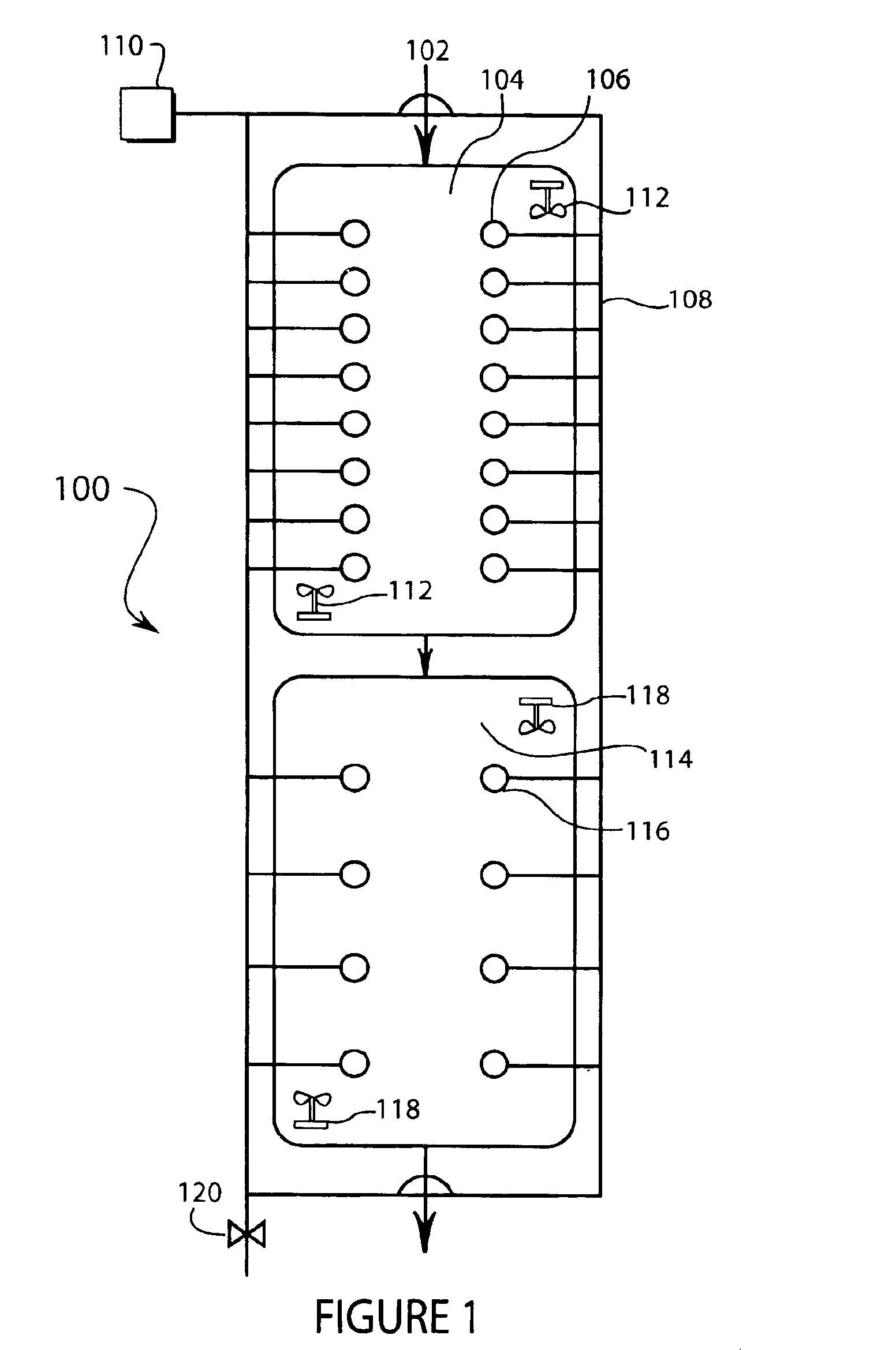
[0029]FIG. 1 is an illustration of an embodiment 100 of the present invention comprising a two lagoon digestion system. Effluent is introduced by arrow 102 into primary lagoon 104. Primary lagoon 104 is outfitted with several air diffusers 106 that are fed by manifold 108 that is supplied by air supply 110. Primary lagoon 104 is further outfitted with surface circulators 112. Secondary lagoon 114 is fed by the overflow of primary lagoon 104, and has a set of air diffusers 116 connected to manifold 108. Secondary lagoon 114 is further outfitted with surface circulators 118. A blow off valve 120 is part of manifold 108.
[0030]The principle of operation of embodiment 100 is to introduce raw or filtered effluent, such as from a dairy, into a lagoon for digestion. The lagoon is inoculated with microbes and has a source of oxygen. Several bottom mounted fine bubble diffusers introduce oxygen into the lagoon. The diffusers serve an additional purpose of forced vertical circulation. Surface ...
embodiment 200
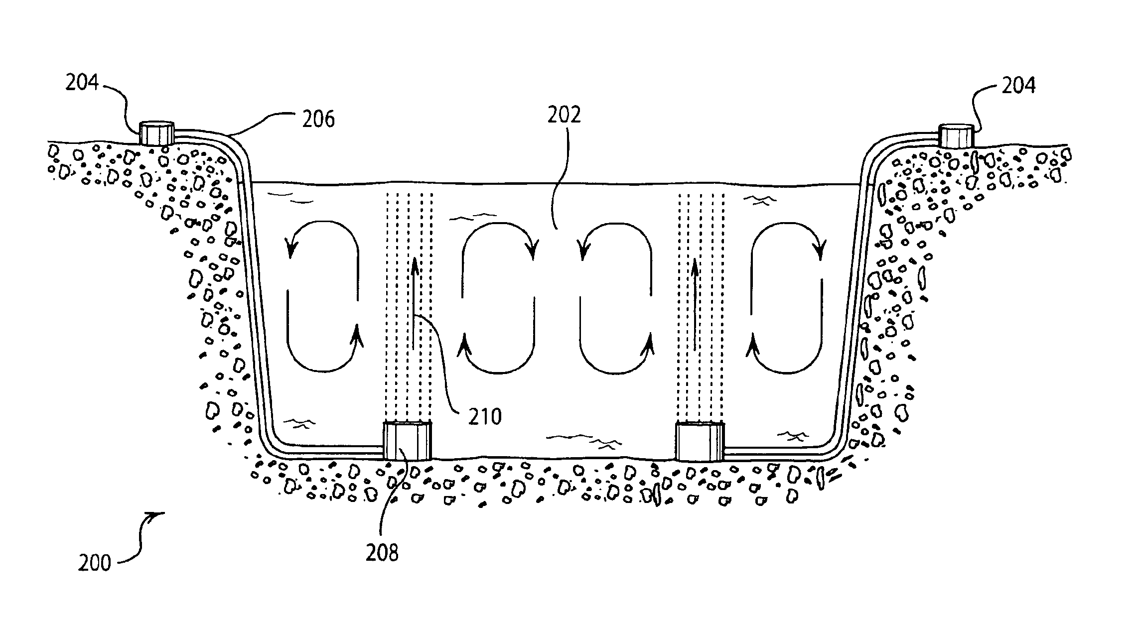
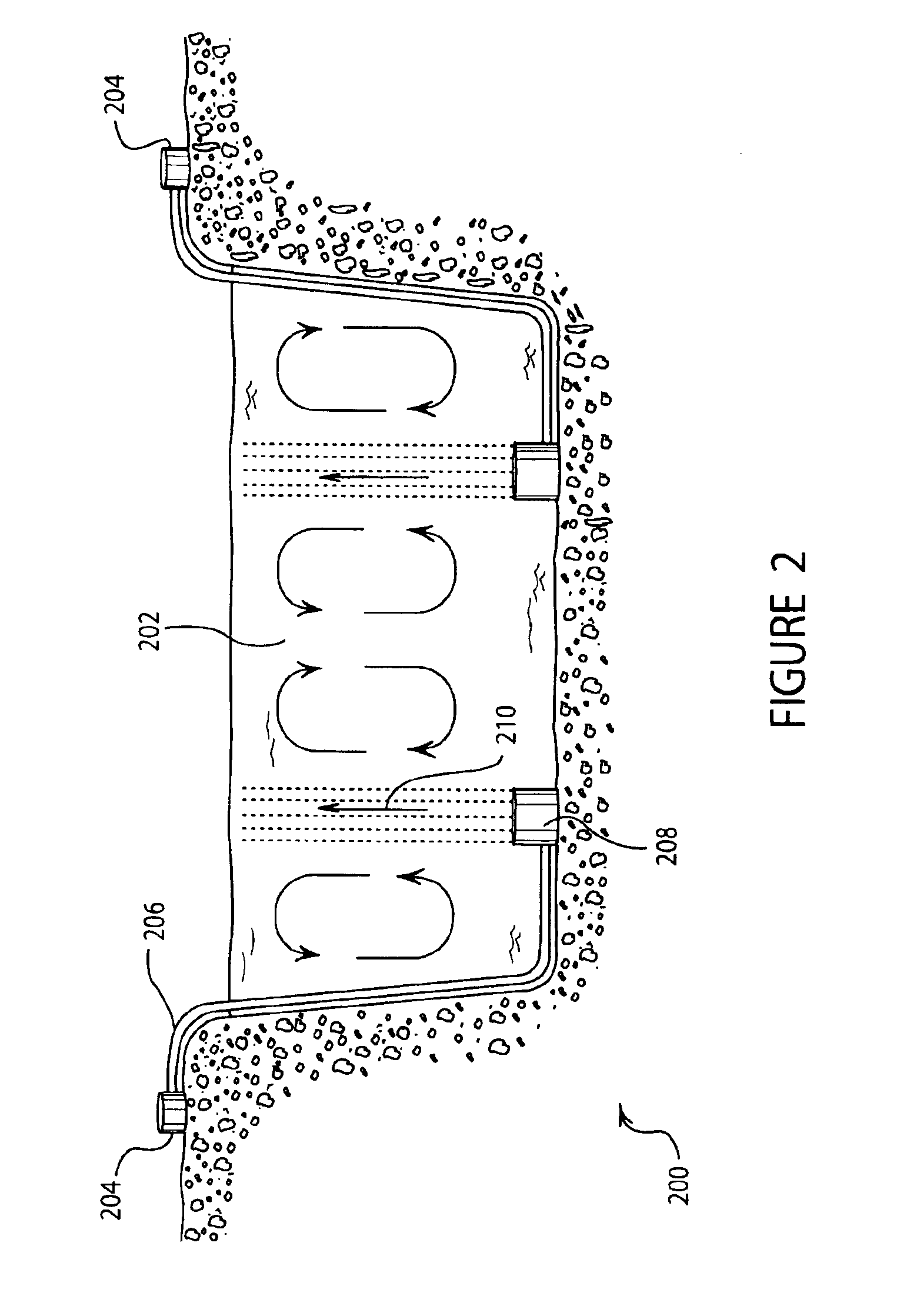
[0041]FIG. 2 is an illustration an embodiment 200 of a cross-section of a typical lagoon 202. A manifold 204 is connected to a pipe 206 that is in communication with a diffuser 208. The bottom-mounted diffuser 208 is adapted to produce a laminar column of fine bubbles 210.
[0042]The lagoon 202 may be approximately 10 to 20 feet deep and may have a clay bottom or other construction to prevent leakage. In some cases, the lagoon 202 may have a plastic or rubber liner to prevent leaking. The lagoon may be 50-300 feet wide, depending on the application. Other sizes of lagoons may be used without deviating from the spirit of the present invention.
[0043]The manifold 204 may be mounted above ground as in FIG. 2, or may be mounted below ground. The manifold may be constructed of PVC piping, steel piping, or any other type of pipe as desired. In some cases, the compressed air is very hot and causes problems with the manifold piping.
[0044]The pipe 206 is preferably a self weighted tubing, with ...
embodiment 300
[0050]FIG. 3 is an illustration of a top view of an embodiment 300 of the present invention wherein four lagoons are used in series to treat effluent. The effluent is introduced into the primary lagoon 302 through the inlet 304. A circulator 306 provides horizontal circulation for primary lagoon 302. The outlet 308 connects primary lagoon 302 to secondary lagoon 310. A circulator 312 provides horizontal circulation for secondary lagoon 312. The outlet 314 connects secondary lagoon 310 to tertiary lagoon 316. A circulator 318 provides horizontal circulation of tertiary lagoon 316. The outlet 320 connects tertiary lagoon 316 to final lagoon 322. A circulator 324 provides horizontal circulation of final lagoon 322. The product water exits the system through outlet 326.
[0051]Primary lagoon 302 has a drain 328 that is connected to sludge pit 330. Secondary lagoon 310 has a drain 332 connected to sludge pit 330. Tertiary lagoon 316 has a drain 334 connected to sludge pit 330, and final la...
PUM
 Abstract
Description
Claims
Application Information
 - R&D
- Intellectual Property
- Life Sciences
- Materials
- Tech Scout
- Unparalleled Data Quality
- Higher Quality Content
- 60% Fewer Hallucinations
Browse by: Latest US Patents, China's latest patents, Technical Efficacy Thesaurus, Application Domain, Technology Topic, Popular Technical Reports.
© 2025 PatSnap. All rights reserved.Legal|Privacy policy|Modern Slavery Act Transparency Statement|Sitemap|About US| Contact US: help@patsnap.com