
Electrical device including a voltage regulator mounted on a variable resistor

a voltage regulator and variable resistor technology, applied in the direction of secondary cell servicing/maintenance, semiconductor/solid-state device details, safety/protection circuit, etc., can solve the problems of dangerous operation of rechargeable lithium battery cells, dangerous rechargeable elements, battery explosion, etc., and achieve low leakage

Inactive Publication Date: 2005-07-05
LITTELFUSE INC
View PDF54 Cites 61 Cited by
  • Summary
  • Abstract
  • Description
  • Claims
  • Application Information

AI Technical Summary

Benefits of technology

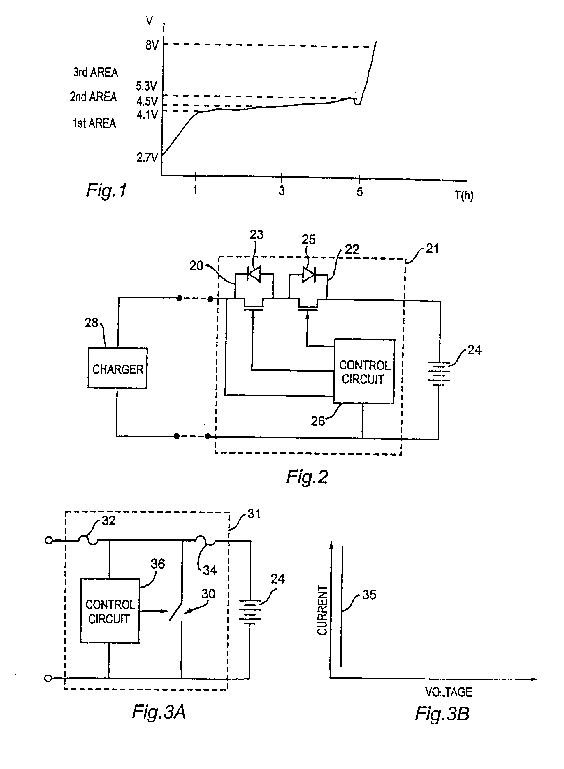
[0021]In accordance with another aspect of the inventions disclosed herein, control circuitry for controlling a shunt regulator transistor switch in a protection circuit for use with a charger and a chargeable element includes first and second voltage detection circuits. The first voltage detection circuit is relatively low leakage and is configured to activate the second voltage detection circuit if the voltage across the chargeable element approaches a threshold ON voltage of the transistor switch. The second voltage detection circuit is relatively precise and is configured to activate the transistor switch if the voltage across the chargeable element reaches the threshold ON voltage.

Problems solved by technology

However, such rechargeable elements, and in particular rechargeable lithium battery cells, can be dangerous if the operating voltage exceeds a safe limit.
When charging is in this area, the battery begins to operate in a dangerous mode, with the temperature rising above 70° C., and the pressure inside the battery rising to a range between 3 bars to 10 bars.
Even at this slightly increased voltage level, the battery might even explode.
At this stage, it is too late to save the battery, which is subjected to internal degradation and may explode or combust.
Notably, battery cells in a “fully-charged” state are more dangerous and susceptible to explosion than those in the discharged state.
As will be appreciated by those skilled in the art, the smart protection circuit 21 is relatively complex and expensive to implement with respect to the overall expense of a conventional battery pack.
However, when the composition is exposed to a high temperature due, for example, to ohmic heating from a high current condition, the resistivity of the composition increases, or “switches,” often by several orders of magnitude.
However, the combined in-series resistance of the overcurrent elements 32 and 34 is undesirable across the battery path.

Method used


Image

  • Electrical device including a voltage regulator mounted on a variable resistor
  • Electrical device including a voltage regulator mounted on a variable resistor
  • Electrical device including a voltage regulator mounted on a variable resistor

Examples


embodiment 37

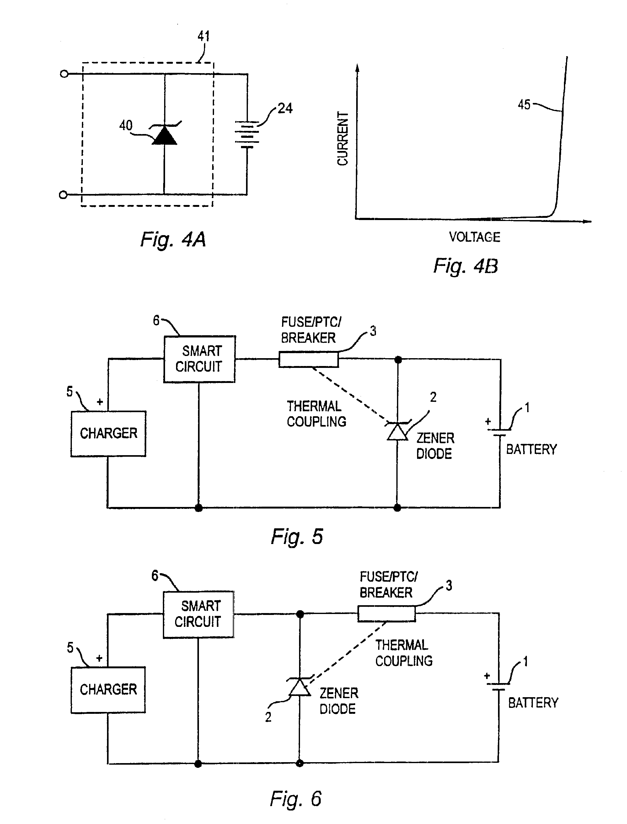
[0104]As will be apparent to those skilled in the art, the PTC device 38 may equally be deployed in the ground path of the battery charging circuit, as shown in the alternate protection circuit embodiment 37′ of FIG. 13. As is explained in greater detail herein, a design choice between embodiments 37 and 37′ will hinge on how the thermal link 48 between the PTC device 38 and regulator 39 is physically manifested.

[0105]In either embodiment 37 or 37′, the PTC device 38 also serves to protect against an overcurrent caused by a sudden charging or discharging of the battery cell(s) 24. In particular, should there be a sudden rise in the current, the PTC device 38 will experience rapid ohmic heating from the sudden surge in dissipated power, until it trips and substantially chokes back on the current.

[0106]Importantly, in order to provide for efficient charging and discharging of the battery cell(s) 24, the in-series resistance of the PTC device 38 and leakage of the regulator device 39 a...

embodiment 340

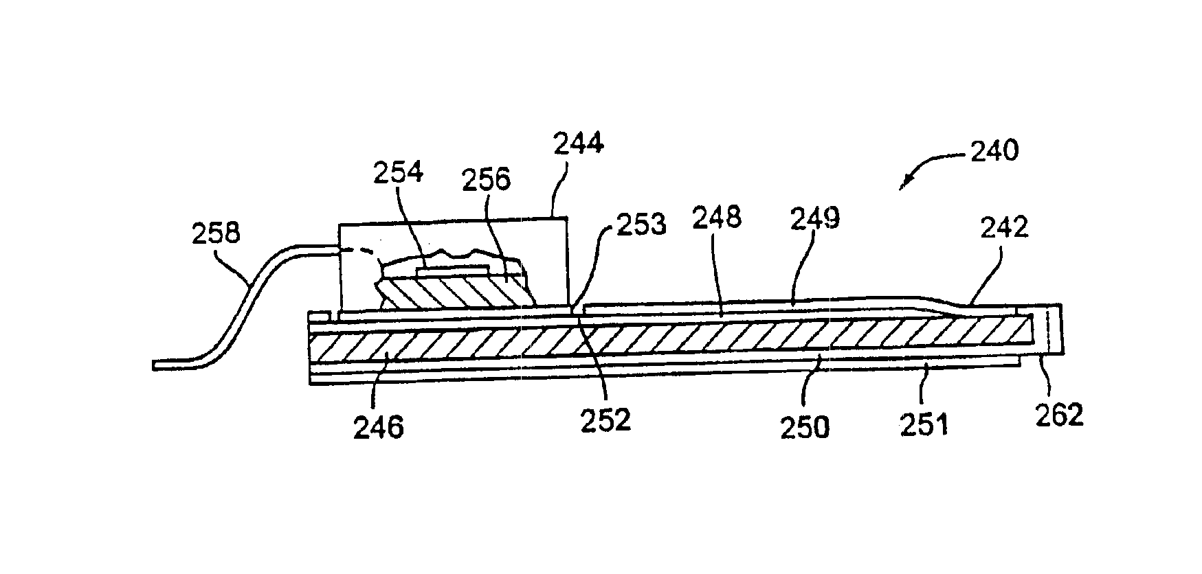
[0218]FIGS. 57-58 depict an alternate preferred embodiment 340 of the above-described three terminal protection device 240. Like protection device 240, protection device 340 includes a PTC chip 342, which is thermally and electrically coupled to a MOSFET regulator 344. The PTC chip 342 includes a layer of PTC material 346 having a first metal electrode layer 348 covering a first side, and a second metal electrode layer 350 covering a second (i.e., opposite) side. The metal electrode layers 348 and 350 are respectively coated with an insulating film 349 and 351.

[0219]As in device 240, a portion of the insulating film 351 is missing at one end of the PTC chip 342, exposing a portion of the metal electrode layer 350, which forms a first terminal 341 of the protection package 340. Unlike in device 240, a portion of the insulating film 351 is also missing at the other end of the PTC chip 342, exposing a portion of a via 363 of metal electrode layer 348, which forms a second terminal 361 ...


PUM

PropertyMeasurementUnit
voltageaaaaaaaaaa
pressureaaaaaaaaaa
temperatureaaaaaaaaaa

Abstract

A protection circuit for use with a charger and a chargeable element, such as a rechargeable lithium ion battery, comprises a shunt regulator having a threshold ON voltage coupled in parallel across the chargeable element, and a temperature-dependent resistor, e.g., a positive temperature coefficient device, coupled in series between the charger and the chargeable element. The temperature dependent resistor is thermally and electrically coupled to the shunt regulator, wherein the first variable resistor limits current flowing through the shunt regulator if the current reaches a predetermined level less than that which would cause failure of the regulator, due to ohmic heating of the regulator.

Description

RELATED APPLICATION DATA[0001]This application is a continuation-in-part of application Ser. No. 09 / 060,863, filed Apr. 15, 1998 now abandoned, and a continuation-in-part of provisional application Ser. No. 60 / 126,952, filed on Mar. 25, 1999, which are hereby fully incorporated by reference for all they teach and disclose.FIELD OF INVENTION[0002]The present inventions pertain generally to the field of overvoltage and overcurrent protection systems and more specifically to devices and methods for protecting rechargeable elements, such as rechargeable batteries, from overvoltage or overcurrent conditions.BACKGROUND[0003]Electrical circuits that protect rechargeable elements, such as rechargeable battery packs, are well known. However, such rechargeable elements, and in particular rechargeable lithium battery cells, can be dangerous if the operating voltage exceeds a safe limit.[0004]For example, FIG. 1 shows a typical charging curve, i.e., the voltage across the battery vs. time, for ...

Claims


Application Information

Patent Timeline
Patent Type & Authority Patents(United States)
IPC IPC(8): H02H9/04H02J7/00H02H7/18H01M10/44H02H3/20
CPCH02H9/042H02J7/0029H02J7/0031H01L25/16H02H7/18H01L2224/48091H01L2924/1301H01L2224/48247H01L2924/13091H01L2924/13062H01L2924/3011H01L2924/00014H01L2924/00H02J7/00308H02J7/00302H02J7/00304H02J7/00306H02J7/00309
Inventor THOMAS, BRIANBEAUFILS, JEAN-MARCCOGAN, ADRIANDALLEMANGE, BERNARDGOZLAN, GILLESLUAN, JIYUANTHORNTON, NEILLTOTH, JAMES
Owner LITTELFUSE INC
Learn More