High-frequency-signal switching circuit suppressing high-frequency-signal distortion

a high-frequency signal and switching circuit technology, applied in the field can solve the problems of high manufacturing cost of high-frequency signal switching circuits b>30/b>, and achieve the effect of suppressing distortion and reducing signal transfer loss

Inactive Publication Date: 2005-06-07
ALPS ALPINE CO LTD
View PDF6 Cites 6 Cited by
  • Summary
  • Abstract
  • Description
  • Claims
  • Application Information

AI Technical Summary

Benefits of technology

[0020]The present invention has been made in consideration of such a technical background. Accordingly, it is an object of the present invention to provide a high-frequency-signal switching circuit which reduces a signal transfer loss in a weak-electric-field state and relatively expensive circuit components and which makes the off bias value of a diode deep to suppress a distortion in a high-frequency signal.

Problems solved by technology

In addition, since relatively expensive circuit components, such as the high-frequency field-effect transistor 321, are required to make the second high-frequency-signal path 32, the manufacturing cost of the high-frequency-signal switching circuit 30 becomes high.

Method used


Image

  • High-frequency-signal switching circuit suppressing high-frequency-signal distortion
  • High-frequency-signal switching circuit suppressing high-frequency-signal distortion
  • High-frequency-signal switching circuit suppressing high-frequency-signal distortion

Examples


Embodiment Construction

[0028]An embodiment of the present invention will be described below by referring to the drawings.

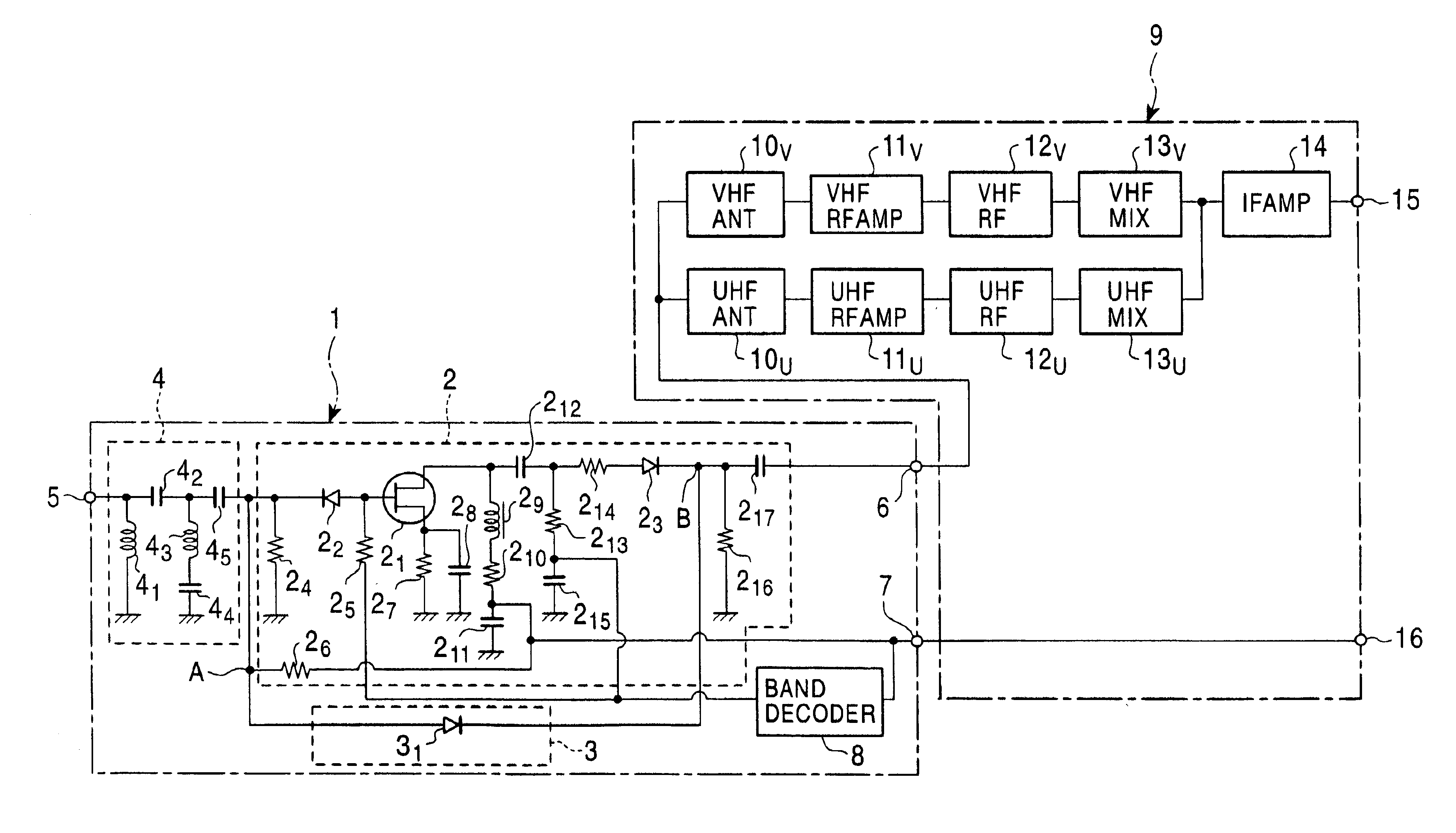
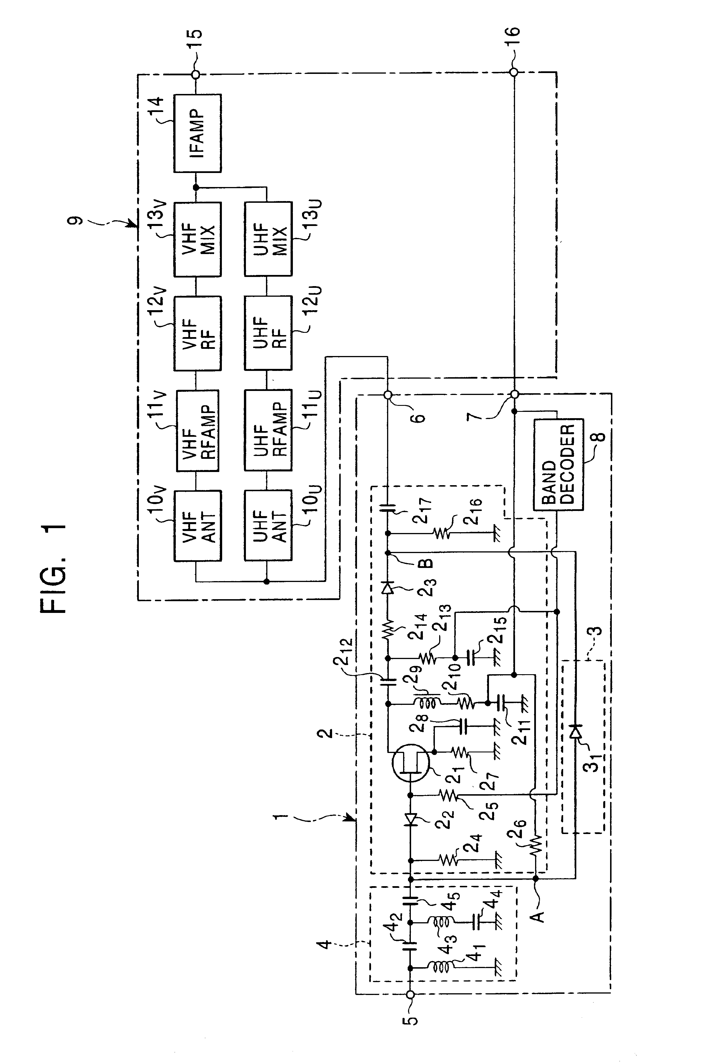
[0029]FIG. 1 is a circuit diagram of a high-frequency-signal switching circuit according to an embodiment of the present invention. A tuner in a TV set is also shown in the figure.

[0030]As shown in FIG. 1, the high-frequency-signal switching circuit 1 is formed of a first high-frequency-signal path 2, a second high-frequency-signal path 3, an input coupling circuit 4, a high-frequency-signal input terminal 5, a high-frequency-signal output terminal 6, a power-supply terminal 7, and a band decoder (switching-voltage supply section) 8.

[0031]The first high-frequency-signal path 2 is formed of an amplification field-effect transistor (FET) 21, a first diode 22, a second diode 23, bias-voltage setting resistors 24, 25, and 26, a source resistor 27, a bypass capacitor 28, a load inductor 29, a load resistor 210, bypass capacitors 211 and 215, a DC-blocking capacitors 212 and 217, and bias-vol...


PUM


Abstract

A high-frequency-signal switching circuit includes a first high-frequency-signal path which includes first and second diodes connected in series with a high-frequency amplifier stage therebetween, and a second high-frequency-signal path formed of a third diode connected in parallel to the first high-frequency-signal path. A switching-voltage supply section switches the high-frequency amplifier stage and first and second diodes ON, and the third diode OFF, so that a high-frequency signal is transferred through the first high-frequency-signal path, or switches the high-frequency amplifier stage and first and second diodes OFF and the third diode ON, so that a high-frequency signal is transferred through the second high-frequency-signal path.

Description

BACKGROUND OF THE INVENTION[0001]1. Field of the Invention[0002]The present invention relates to high-frequency-signal switching circuits, and more particularly, to a high-frequency-signal switching circuit which is connected to the input end of a TV-set tuner, which can be switched between when a strong electric field is input and when a weak electric field is input, and which has a reduced high-frequency-signal transfer loss and a reduced number of necessary components.[0003]2. Description of the Related Art[0004]There has been known a high-frequency-signal switching circuit connected to the input end of a TV-set tuner in order to handle both a strong-electric-field state and a weak-electric-field state. The high-frequency-signal switching circuit has a first high-frequency-signal path in which a high-frequency signal is transferred through a high-frequency amplifier stage, and a second high-frequency-signal path in which a high-frequency signal bypasses the high-frequency amplifi...

Claims


Application Information

Patent Timeline
Patent Type & Authority Patents(United States)
IPC IPC(8): H03G1/00H03G3/00H01P1/15H03F3/193H04N5/44
CPCH03G3/001H03G1/0088H04N5/208
Inventor YAMAMOTO, MASAKI
Owner ALPS ALPINE CO LTD
Why Eureka
Try Eureka