
Vibratory double-axially sensing micro-gyroscope

a micro-gyroscope and vibration-sensitive technology, applied in the direction of acceleration measurement using interia force, turn-sensitive devices, instruments, etc., can solve the problems of common mems technology and the inability to meet design requirements, and achieve excellent resistance to environmental noise and vibration, enhance sensing ability, and reduce cost

Inactive Publication Date: 2005-06-07
IND TECH RES INST
View PDF5 Cites 29 Cited by
  • Summary
  • Abstract
  • Description
  • Claims
  • Application Information

AI Technical Summary

Benefits of technology

The invention is a vibratory double-axially sensing micro-gyroscope that has a beam-typed and symmetrical structure, allowing it to sense in both the X and Y directions. It is stable and resistant to environmental noise and vibration, improving its sensing ability. It can also be produced using MEMS technology, reducing costs. Additionally, it has a sensing mode frequency close to the driving mode frequency, enhancing its sensitivity.

Problems solved by technology

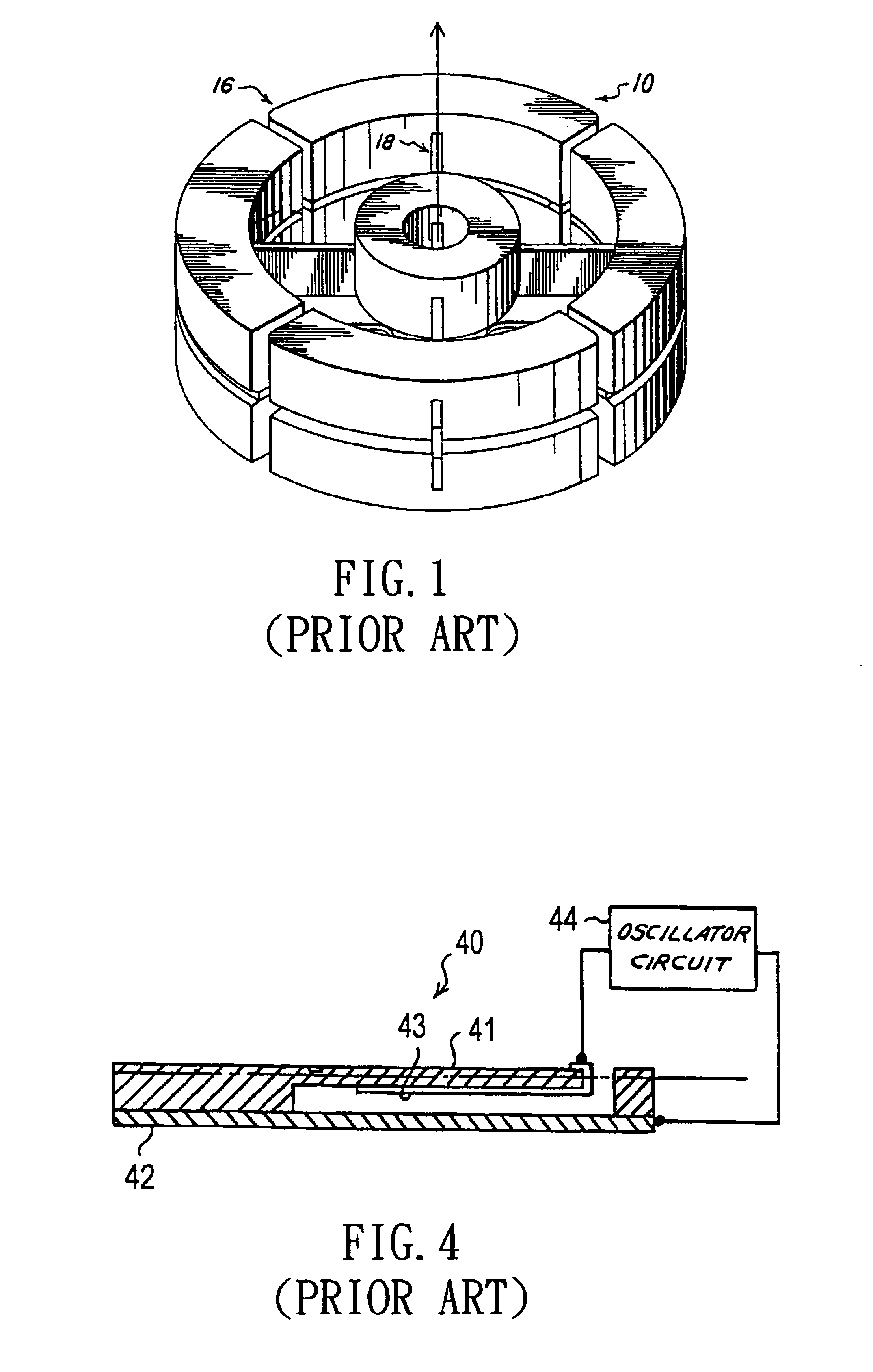
Traditional rotor-typed gyroscope 10 is designed by applying the conservation principle of angular momentum so as to obtain the angular speed of rotation, so there are many problems involving complicated structures and bearing friction, such that there are many shortcoming existing in traditional gyroscope, such as: expansive price, heavy weight, and short lifetime, etc.
This design can not be fulfilled by common MEMS technology.

Method used


Image

  • Vibratory double-axially sensing micro-gyroscope
  • Vibratory double-axially sensing micro-gyroscope
  • Vibratory double-axially sensing micro-gyroscope

Examples


Embodiment Construction

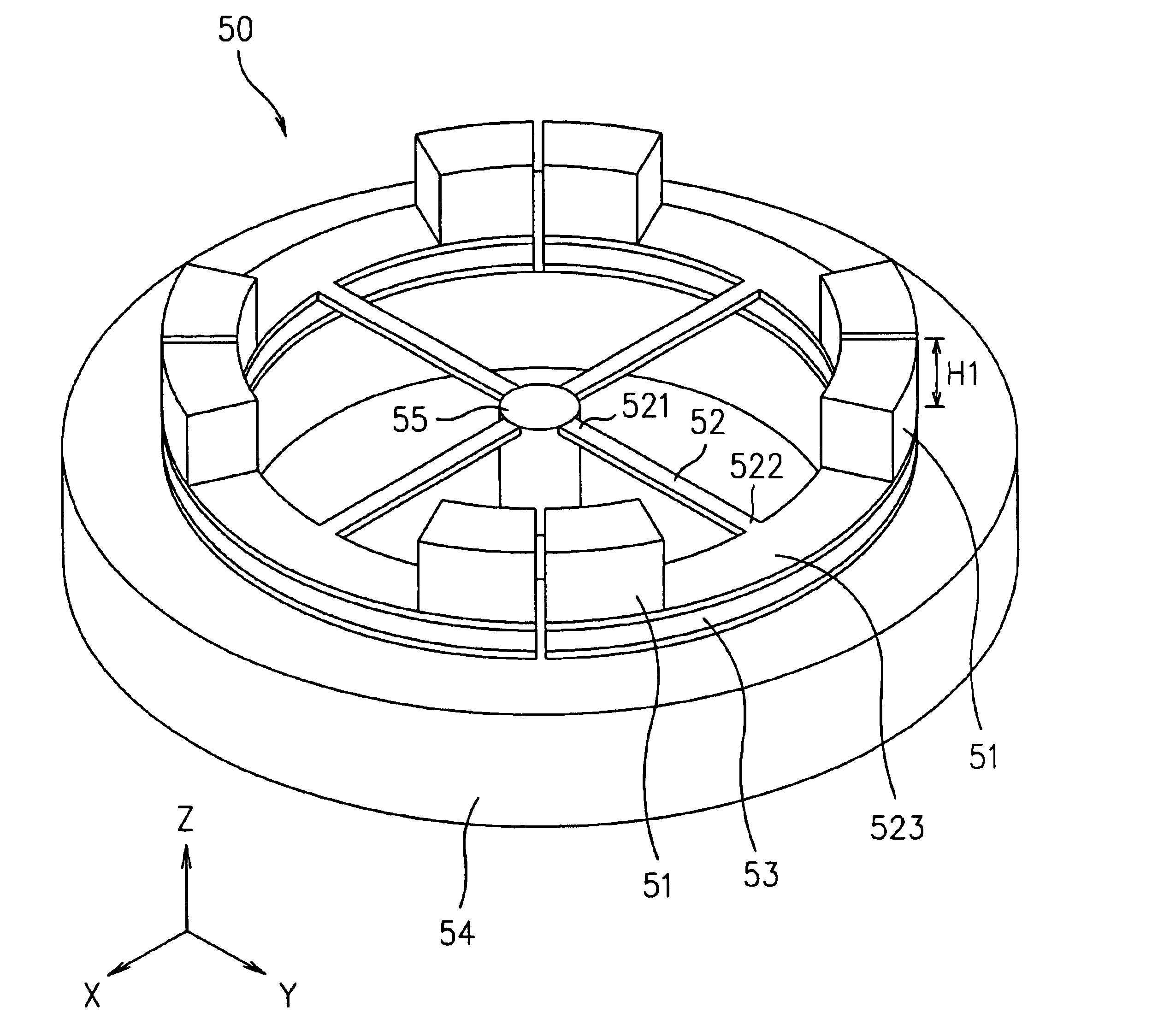
[0024]Please refer FIG. 5 to FIG. 7, which are 3-D outer-appearance views for a preferable embodiment according to the present invention. Wherein, a beam-typed vibratory gyroscope 50, driven by static-electricity and sensing with capacitance manner, has a ring-typed base 54, at center of which a supporting hub 55 is arranged. Plural suspending arms 52, arranged around the supporting hub 55, are extended horizontally with equal altitude in radial direction by taking the supporting hub 55 as center. The arrangement of the suspending arm 52 is at least two or even-numbered. Inside end 521 of the suspending arm 52 is connected to the supporting hub 55. Outside end 522 of the suspending arm 52 is extended horizontally toward two sides by taking the suspending arm 52 as center to form a platform 523. In this preferable embodiment of the invention, four suspending arms 52 are arranged and each suspending arm 52 has a platform 523. Four platforms 523 have same curvature. A discontinuous rin...


PUM


Abstract

The invention is to provide a vibratory double-axially sensing micro-gyroscope, which includes a base, on center of which a supporting hub is arranged, and plural suspending arms are extended outwardly with equal altitude and in radial direction from the supporting hub and, at the outside end of the suspending arm, a platform is formed, and a capacitance sensing electrode or a static-electricity driving electrode is plated respectively at each side of the platform top, below which a static-electricity driving electrode or a capacitance sensing electrode is arranged; take a preferred embodiment of the present invention for example, if the capacitance sensing electrode is arranged at top of the platform and the static-electricity driving electrode is arranged below the platform, then the suspending arm and the platform will vibrate vertically by the attraction of the static-electricity when applying driving voltage, and the vibratory phase difference between two adjacent suspending arms and the platform is 180 degrees; when the gyroscope is rotated horizontally, the suspending arm and the platform will generate horizontal displacement caused by Coriolis force and, by measuring the change of capacitance value, the magnitude of the angular velocity of vibration is obtained; since its structure has symmetrical property, so it has sensing ability in both X or Y axes and, because it has superior stability and is able to resist environment noise and vibration, its sensing capability is enhanced and, since its machining method is simple, so it is adapted for mass production for having lower manufacturing cost.

Description

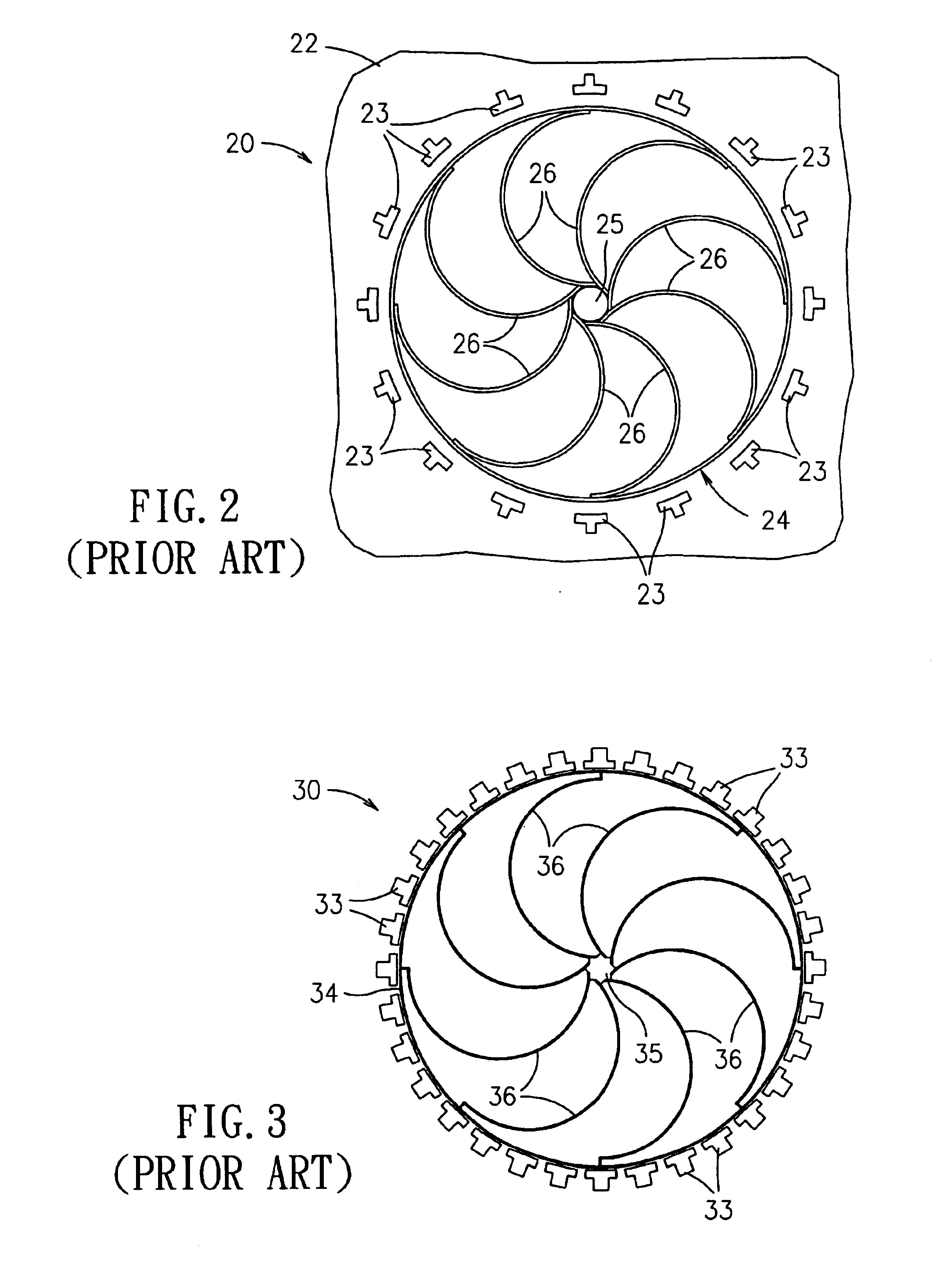
[0001]This Nonprovisional application claims priority under 35 U.S.C. §119(a) on Patent Application No(s). 092120314 filed in TAIWAN on Jul. 25, 2003, the entire contents of which are hereby incorporated by reference.FIELD OF THE INVENTION[0002]The invention relates to a vibratory double-axially sensing micro-gyroscope, and in particular to a static-electricity driving harmonic gyroscope that is belonged to beam type, symmetrically structured, and capable of double-axial sensing in X or Y direction.BACKGROUND OF THE INVENTION[0003]Gyroscope, an apparatus applying inertia principle to measure rotary angle or angular velocity, is mainly applied in the guidance of military, aviation, and navigation, etc. According to operational principle, gyroscope may be divided to two kinds: rotor-typed gyroscope and vibratory gyroscope driven by static electricity.[0004]As shown in FIG. 1, which is a single-axial beam-typed gyroscope (U.S. Pat. No. 4,499,778: Flexure Mount Assembly for A Dynamicall...

Claims


Application Information

Patent Timeline
Patent Type & Authority Patents(United States)
IPC IPC(8): G01C19/56G01P9/04
CPCG01C19/56Y10T74/1275
Inventor CHEN, YI-RUCHANG, KAI-CHENGFANG, GUANG-CHYENGHSU, MING-HSIULIANG, PEI-FANG
Owner IND TECH RES INST
Learn More