
Integrated sensor

a sensor and integrated technology, applied in the field of molecular species detection, can solve the problems of limiting the size and flexibility of such on-chip devices, scaling down existing technologies such as fluorescent measurement schemes, to the chip scale does not provide effective solutions, and limits the robustness of current technologies, so as to avoid mixing steps during sample preparation

Inactive Publication Date: 2005-05-31
RGT UNIV OF CALIFORNIA
View PDF7 Cites 20 Cited by
  • Summary
  • Abstract
  • Description
  • Claims
  • Application Information

AI Technical Summary

Benefits of technology

The present invention provides an integrated optical sensor for on-chip analysis of immunoassays and molecular diagnostics. The sensor measures minute changes in the index of refraction, which can be caused by a specific chemical reaction or antigen-antibody binding. Unlike other related art devices, the present invention does not require mixing of conjugate antibodies or fluorescent molecules during sample preparation, and it does not require external devices such as external light sources, fluorescent filters, or external recording optics. The sensor operates at the microscopic scale and has sensitivities that can detect single molecules. It is flip chip bonded to a microfluidic chip and uses a tunable laser cavity sensor (TLCS) that detects the presence of a molecule by a heterodyned frequency shift.

Problems solved by technology

The systems require the mixing of conjugate antibodies or the use of fluorescent antibodies or hybridizing fluorescent molecules during preparation, and, while being miniaturized nevertheless still require macroscopic techniques such as external light sources, external electro-optical detectors, and electronic instrumentation, all of which significantly limit the size and flexibility of such on-chip devices.
Simply scaling down existing technologies, such as fluorescent measurement schemes, to the chip scale does not provide effective solutions.
Moreover, any new technology must minimize meticulous sample preparation and handling steps, which limits the robustness of current technologies.
Although an attempt at integrated system is provided by U.S. Pat. No. 5,637,458, it does not entirely provide a fully integrated optical chip device.

Method used


Image

  • Integrated sensor
  • Integrated sensor
  • Integrated sensor

Examples


Embodiment Construction

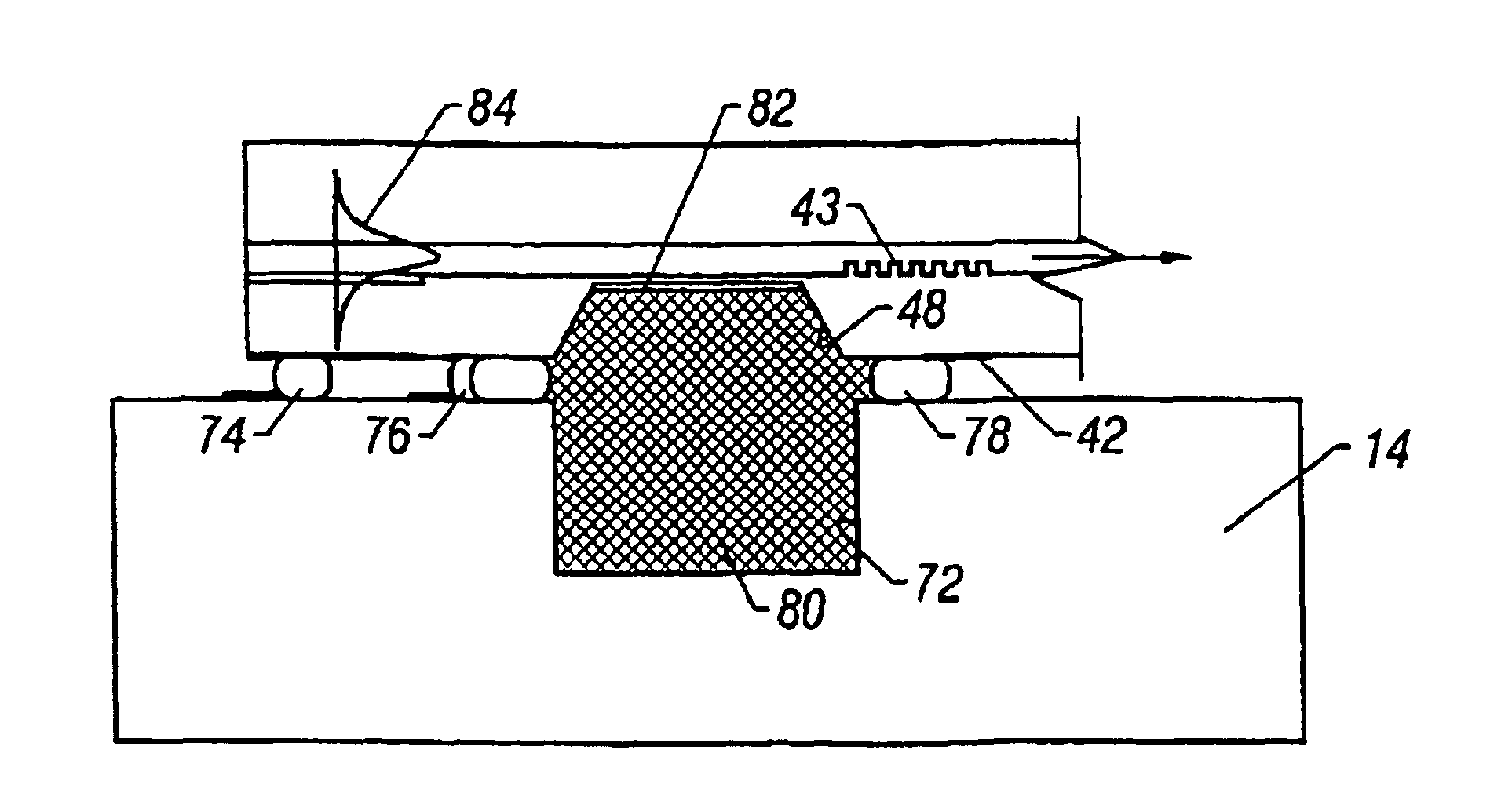
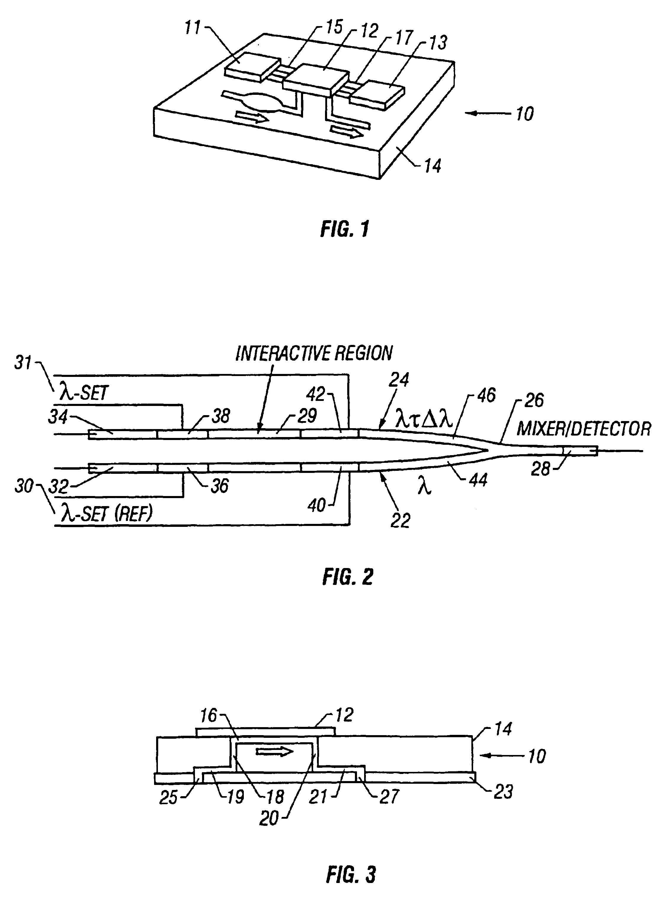
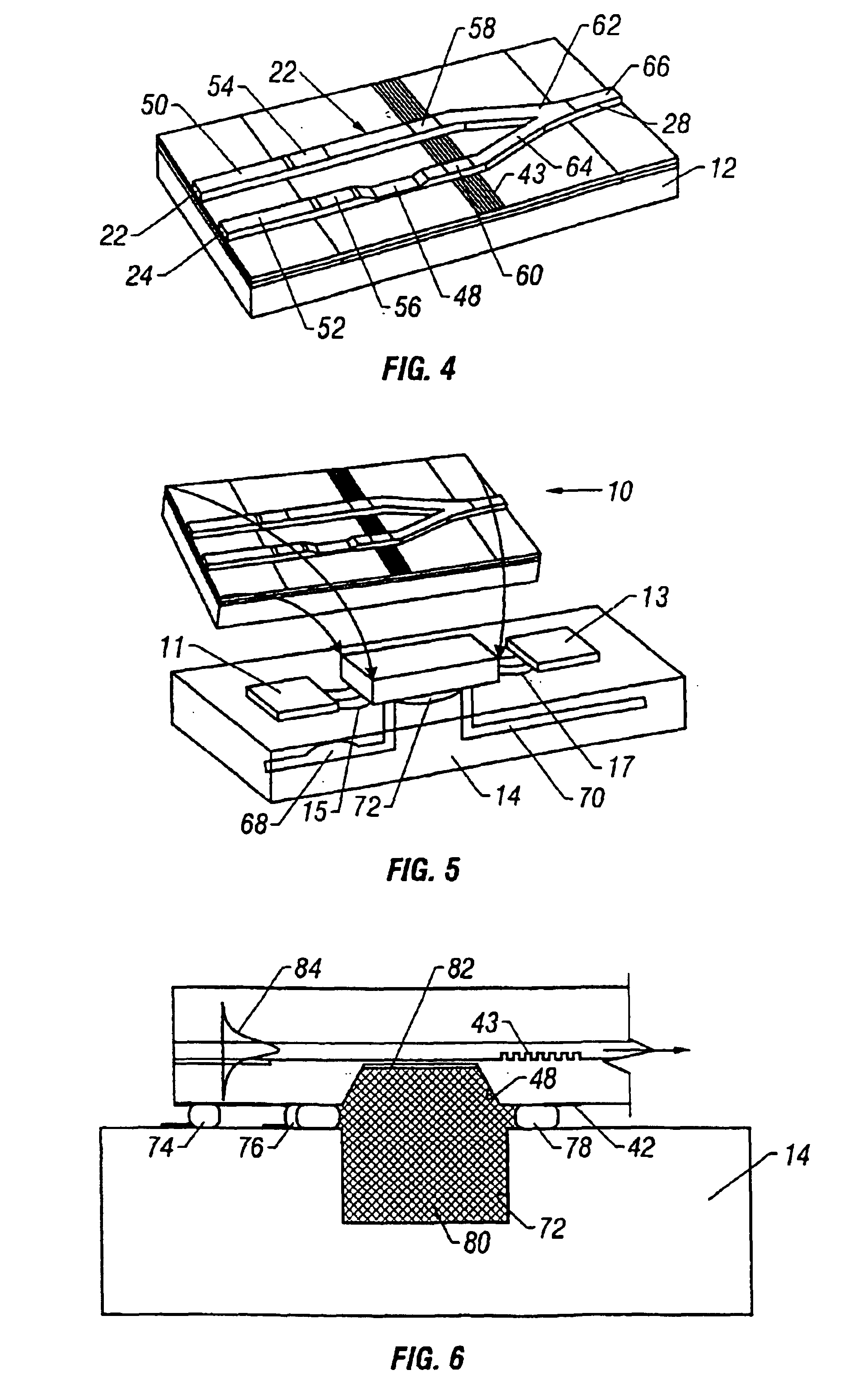
[0025]Referring to FIG. 1 an integrated optical chip device 10 in accordance with this invention is formed by flip-chip bonding an InP-based laser / detector chip 12 to a Si-biofluidic chip 14. The InP optical sensor chip measures slight frequency shifts due to evanescent wave interactions with fluidic medium in a laser cavity, as will be described in more detail below, and can be referred to as a tunable laser cavity sensor (TLCS).

[0026]Referring additionally to FIG. 3, the biofluidic chip 14 contains a microfabricated flow cell with an opening 16 adjacent a cavity in the sensor chip 12 as will be described below in more detail. Microchannel 18 feeds fluid to the opening 16 and an outlet microchannel 20 removes effluent from the opening 16. The opening 16 and the sensor cavity (not shown in FIGS. 1 and 3) serve as a sample chamber, a diffusion-dominated region, where analyte can diffuse to a wall of the sensor cavity. An adsorbent, such as a capture antibody for immunoassays, or a li...


PUM

PropertyMeasurementUnit
wavelength rangeaaaaaaaaaa
lasing wavelengthsaaaaaaaaaa
frequencyaaaaaaaaaa

Abstract

An integrated optical chip device for molecular diagnostics comprising a tunable laser cavity sensor chip using heterodyned detection at the juncture of a sensor laser and a reference laser, and including a microfluid chip to which the sensor chip is flip-chip bonded to form a sample chamber that includes exposed evanescent field material of the tunable laser cavity to which fluid to be diagnosed is directed.

Description

CROSS-REFERENCE TO RELATED APPLICATION[0001]This application claims the benefit of U.S. Provisional Patent Application Ser. No. 60 / 221,624, filed Jul. 28, 2000.STATEMENT REGARDING FEDERALLY SPONSORED RESEARCH OR DEVELOPMENT[0002]This invention was made with Government Support under Grant No. DAAD19-00-1-0400, awarded by the Department of the Army, and Grant No. N00014-96-1-G014, awarded by the Office of Naval Research. The Government has certain rights in this invention.FIELD OF THE INVENTION[0003]This invention relates to the detection of a molecular species using heterodyned laser light.BACKGROUND OF THE INVENTION[0004]There has been long recognized a desire to automate the analysis of a wide variety of substances including chemical and biochemical materials, contaminants, biological warfare agents, and generally any substance, the presence and / or amount of which is desired to be determined. In recent years, on-chip systems have been developed for molecular diagnostics, e.g., for ...

Claims


Application Information

Patent Timeline
Patent Type & Authority Patents(United States)
IPC IPC(8): G01N21/77G01N21/05G01N21/03G01N21/55G01N21/31G01N21/39
CPCG01N21/05G01N21/552G01N21/7703G01N21/39G01N2021/0346G01N2021/7776Y10S436/805Y10S436/806
Inventor MEINHART, CARL D.COLDREN, LARRY A.STULTZ, TIMOTHY J.
Owner RGT UNIV OF CALIFORNIA
Learn More