
Method and device for the failsafe monitoring of the rotational movement of a shaft

a technology of failsafe monitoring and rotational movement, which is applied in the direction of safety arrangments, instruments, electric digital data processing, etc., can solve the problems of unfavorable shutdown of the press, slowest rotational movement of the shaft, unnecessary and expensive downtime, etc., and achieves greater safety for the operating personnel involved. , the effect of reasonable expenditur

Inactive Publication Date: 2005-05-24
PILZ (COMPANY)
View PDF10 Cites 0 Cited by
  • Summary
  • Abstract
  • Description
  • Claims
  • Application Information

AI Technical Summary

Benefits of technology

[0013]It is therefore an object of the present invention to improve a method and a device of the type stated at the beginning in order to achieve, with reasonable expenditure, still greater safety for the operating personnel involved.
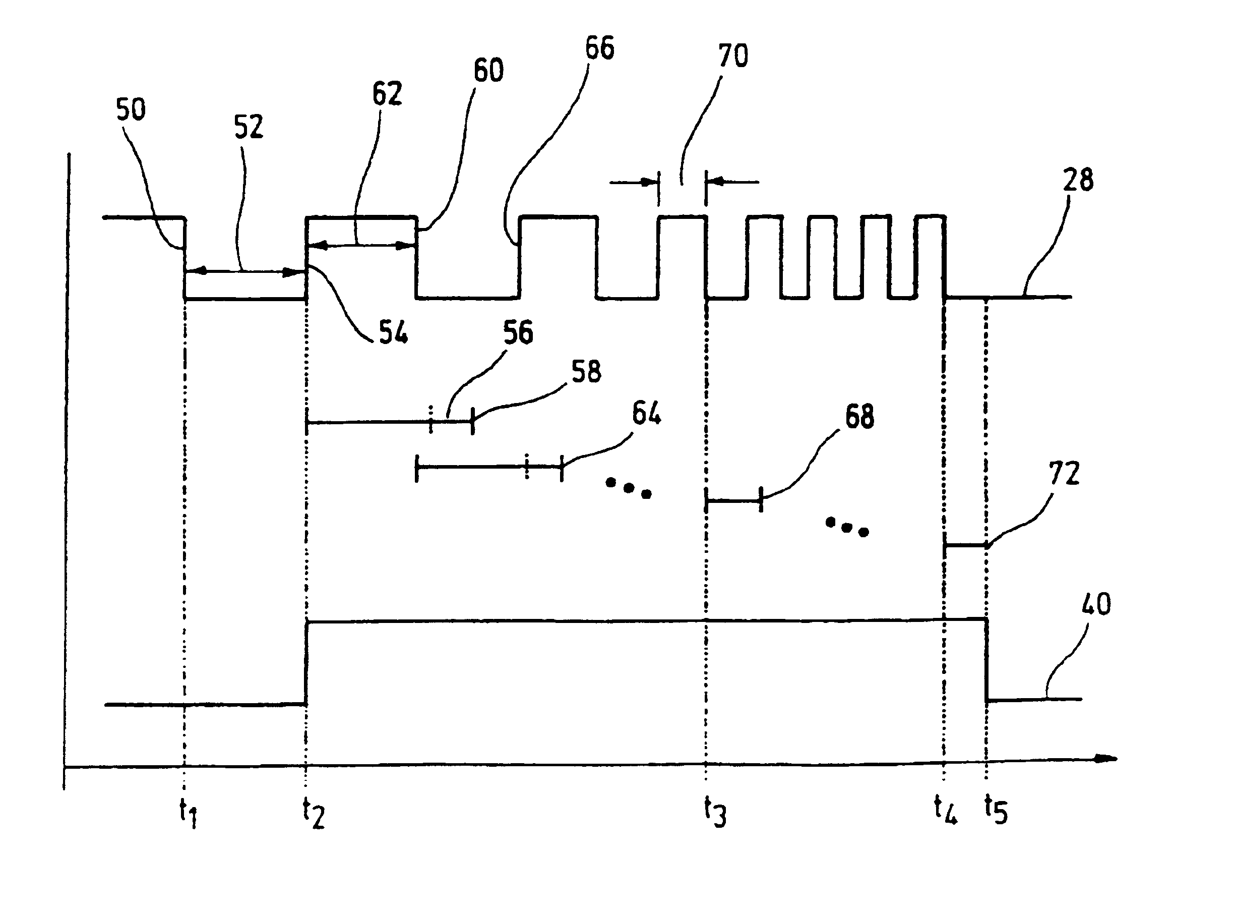
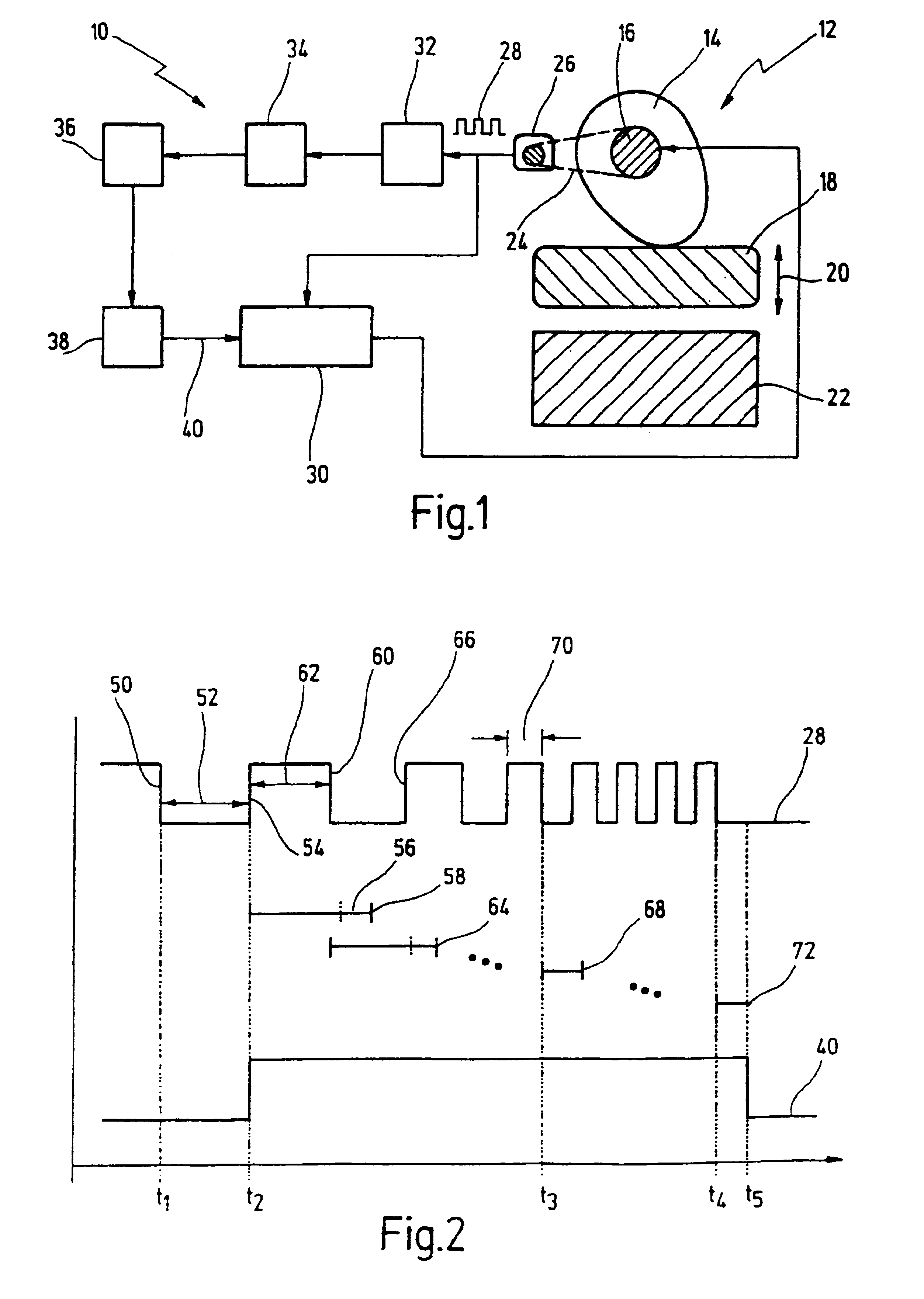
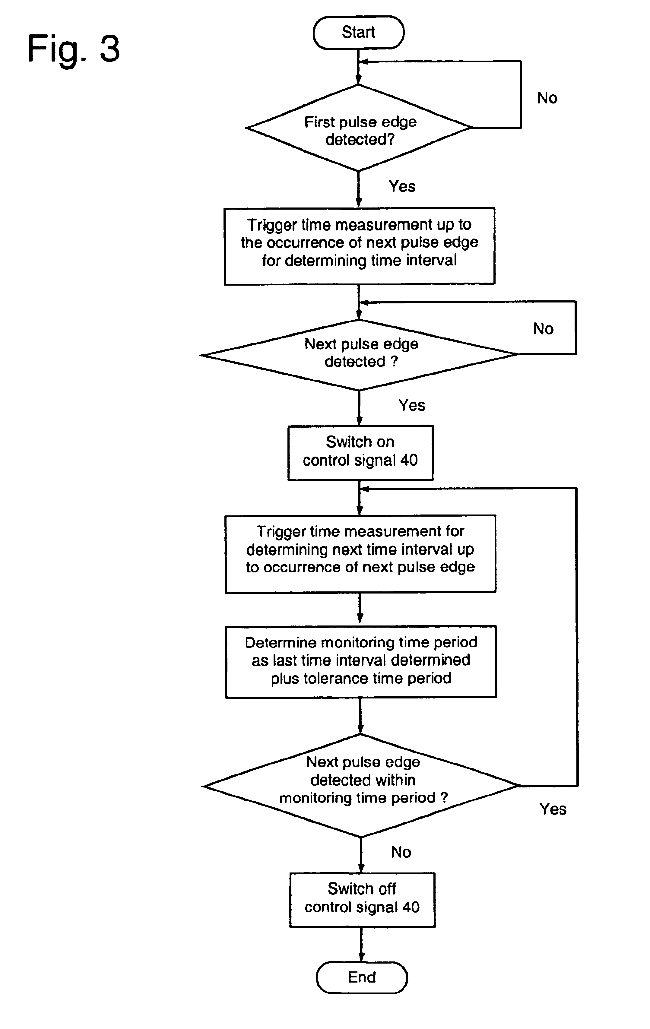
[0015]In contrast to previously known monitoring devices, the monitoring of the pulse train now takes place for the first time in an adaptive manner with regard to the current operating parameters of the monitored machine. The time basis of the monitoring is respectively adapted to the current rotational speed of the shaft. As a consequence, the non-occurrence of an expected pulse is detected with the smallest delay time, irrespective of the current rotational speed of the shaft and consequently irrespective of a number of strokes of the press. The monitoring device can therefore react to a critical failure in a shorter time and shut down the monitored machine, such as for example a press. The shortened reaction times mean greater safety for the operating personnel involved.
[0016]In addition, the previously required manual setting of the monitoring time period on the monitoring device is no longer required. As a result, errors caused by human failure are avoided, which further increases the safety for the operating personnel involved. As a side effect, the installation expenditure or set-up expenditure before the press is put into operation is also reduced.
[0018]As an alternative to this, it would also be possible to determine the monitoring time period as a function of an instantaneous frequency of the pulse train, for instance. The aforementioned measure can be realized more simply and with quicker in operation. This permits further minimization of the reaction times when shutting down a machine.
[0020]This measure permits especially rapid adaptation of the monitoring time period to any change of the rotational movement of the monitored shaft. Consequently, the reaction times of the monitoring device can be minimized still further.
[0024]In this refinement of the invention, the system does not wait for the occurrence of a complete pulse, but instead already monitors the occurrence of each individual pulse edge of the pulse. The occurrence of a complete pulse is virtually doubled-checked. This permits a still more rapid reaction time and consequently contributes once again to an optimization of safety.

Problems solved by technology

In the case of a mechanical press, which is a source of considerable risk to the operating personnel during operation, the pulses of the cam-operated switchgroup must undergo failsafe monitoring to ensure that the press is operating properly.
If the pulses do not occur, an immediate, failsafe shutdown of the press takes place, since otherwise an uncontrolled and consequently dangerous state exists.
This is because, on account of the safety-critical use, the devices have to meet especially high requirements in terms of their intrinsic failsafe nature.
In the case of presses with a variable number of strokes, however, this leads to the problem that the monitoring time period must be set to the smallest number of strokes occurring and consequently to the slowest rotational movement of the shaft.
Otherwise, small numbers of strokes give rise to false alarms, which lead to unnecessary and expensive downtimes. Greater numbers of strokes, however, produce relatively long reaction times when shutting down, which is disadvantageous in an emergency situation.

Method used


Image

  • Method and device for the failsafe monitoring of the rotational movement of a shaft
  • Method and device for the failsafe monitoring of the rotational movement of a shaft
  • Method and device for the failsafe monitoring of the rotational movement of a shaft

Examples


Embodiment Construction

[0030]In FIG. 1, a device according to the invention is designated overall by reference numeral 10.

[0031]The device 10 serves for the failsafe monitoring of the operating sequence of an eccentric press 12, which is only schematically represented here by way of example. Other types of presses might also be envisaged. The press 12 has an eccentric 14, which is arranged on a shaft 16. By means of the shaft / eccentric combination, what is known as a tappet 18 is moved in the direction of an arrow 20. In its lowered position, the tappet 18 interacts with a generally fixed press bed 22, in order to bring a workpiece into a desired form. The construction of such a press is known per se and is therefore not presented any further here.

[0032]In the exemplary embodiment shown, shaft 16 of press 12 is connected to a cam-operated switchgroup 26 by means of a chain 24. As an alternative to chain 24, a toothed belt or a transmission could also be used. Such an arrangement and corresponding cam-oper...


PUM

PropertyMeasurementUnit
timeaaaaaaaaaa
time intervalsaaaaaaaaaa
time periodaaaaaaaaaa

Abstract

A method for the failsafe monitoring of the rotational movement of a shaft comprises a first step of picking up a characteristic pulse train with a number of pulses following one another at successive times, the time interval between the pulses is dependent on the rotational movement. A second step determines a monitoring time period and a third step monitors whether an expected pulse of the pulse train occurs within the monitoring time period. Finally, there is a fourth step of generating a control signal when the expected pulse does not occur within the monitoring time period. The mounting time period is repeatedly adapted to the time interval of the pulses during monitoring.

Description

CROSS-REFERENCES TO RELATED APPLICATIONS[0001]This application is a continuation of copending international patent application PCT / EP02 / 01747 filed on Feb. 19, 2002 designating the U.S., which PCT application is published in German language and claims priority from German patent application DE 101 12 230.6, filed on Mar. 8, 2001.BACKGROUND OF THE INVENTION[0002]The present invention generally relates to a method and device for the failsafe monitoring of the rotational movement of a shaft.[0003]More specifically, the invention relates to a method for the failsafe monitoring of the rotational movement of a shaft, comprising the steps of:[0004]generating a characteristic pulse train with a number of pulses following one another at successive times, the time interval of which is dependent on the rotational movement of the shaft,[0005]determining a monitoring time period,[0006]monitoring whether an expected pulse of the pulse train occurs within the monitoring time period, and[0007]gener...

Claims


Application Information

Patent Timeline
Patent Type & Authority Patents(United States)
IPC IPC(8): G05B23/02B30B15/14F16P3/00B30B15/28G05B9/02
CPCG05B23/0297G05B23/0256
Inventor SCHUMACHER, MANFRED
Owner PILZ (COMPANY)
Learn More