
Spark plug and its manufacturing method

a technology of spark plugs and manufacturing methods, applied in the field of spark plugs, can solve the problems of noble metallic tips falling or peeling off severe thermal load acting on the joint area of the electrode base material, and the reliability of the joint (or bond) becomes so small, and achieves excellent bonding strength, excellent anti-exhaustion properties of noble metallic tips, and satisfactory workability of electrode base materials.

Inactive Publication Date: 2005-04-26
DENSO CORP
View PDF14 Cites 45 Cited by
  • Summary
  • Abstract
  • Description
  • Claims
  • Application Information

AI Technical Summary

Benefits of technology

This solution effectively reduces thermal stress, improves bonding strength, and maintains anti-exhaustion properties and workability of the spark plug, even in high-temperature environments, by forming oxide layers that match the thermal expansion coefficient of the noble metallic tip.

Problems solved by technology

Rapidly increasing and decreasing the plug temperature will cause a severe thermal load acting on the joint area of the electrode base material and the noble metallic tip.
In other words, the margin of joint (or bond) reliability becomes so small that the noble metallic tip may fall or peel off the electrode base material.
However, according to the above-described conventional manufacturing method, the cost will increase due to addition of a thermal treatment.
However, this method includes the following problems.
This will worsen the anti-exhaustion properties of a noble metallic tip and therefore cannot assure a satisfactory life of a spark plug.
This will worsen the bendability (i.e., workability) of an electrode base material.
Such a material cannot be used for a spark plug.

Method used


Image

  • Spark plug and its manufacturing method
  • Spark plug and its manufacturing method
  • Spark plug and its manufacturing method

Examples


Embodiment Construction

[0081]Preferred embodiments of the present invention will be explained hereinafter with reference to attached drawings. Identical parts are denoted by the same reference numerals throughout the drawings.

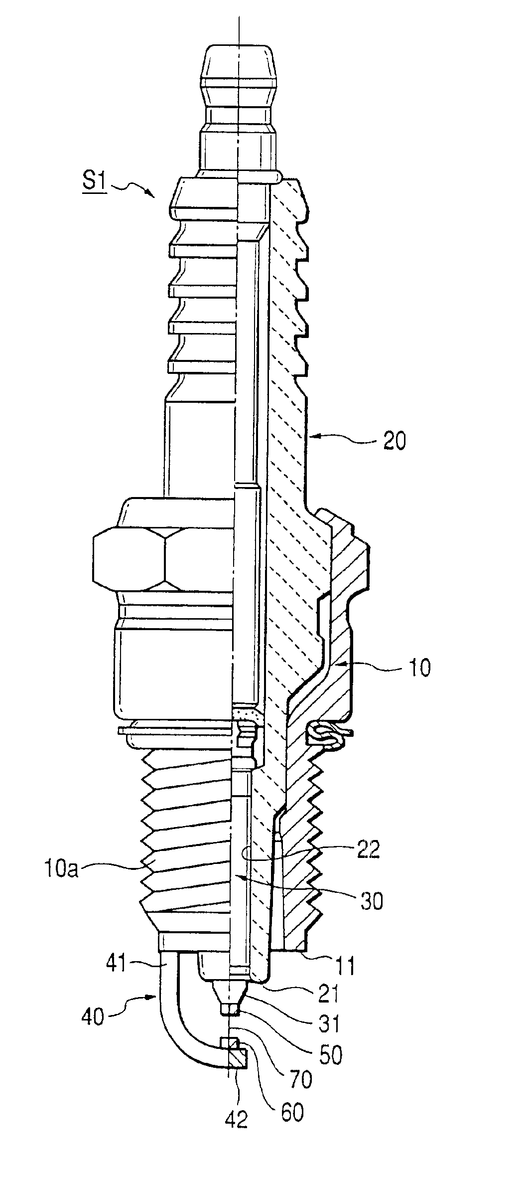
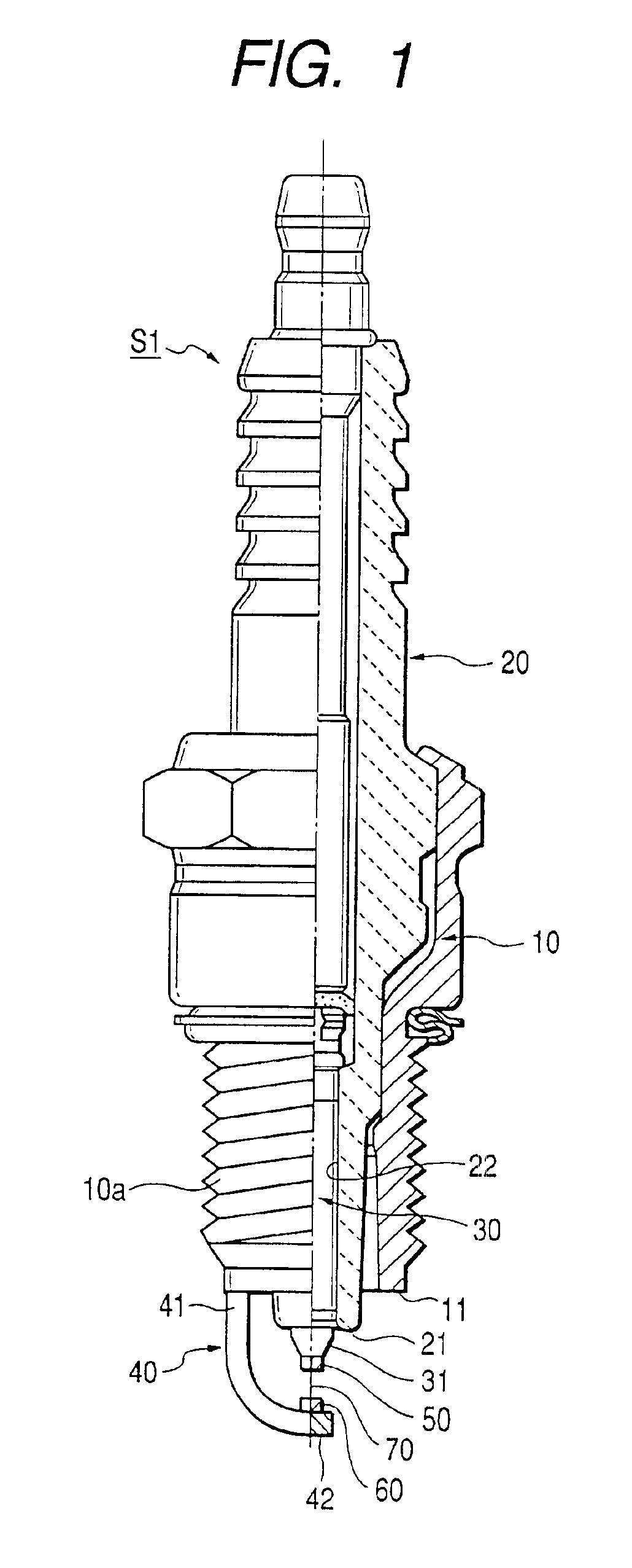
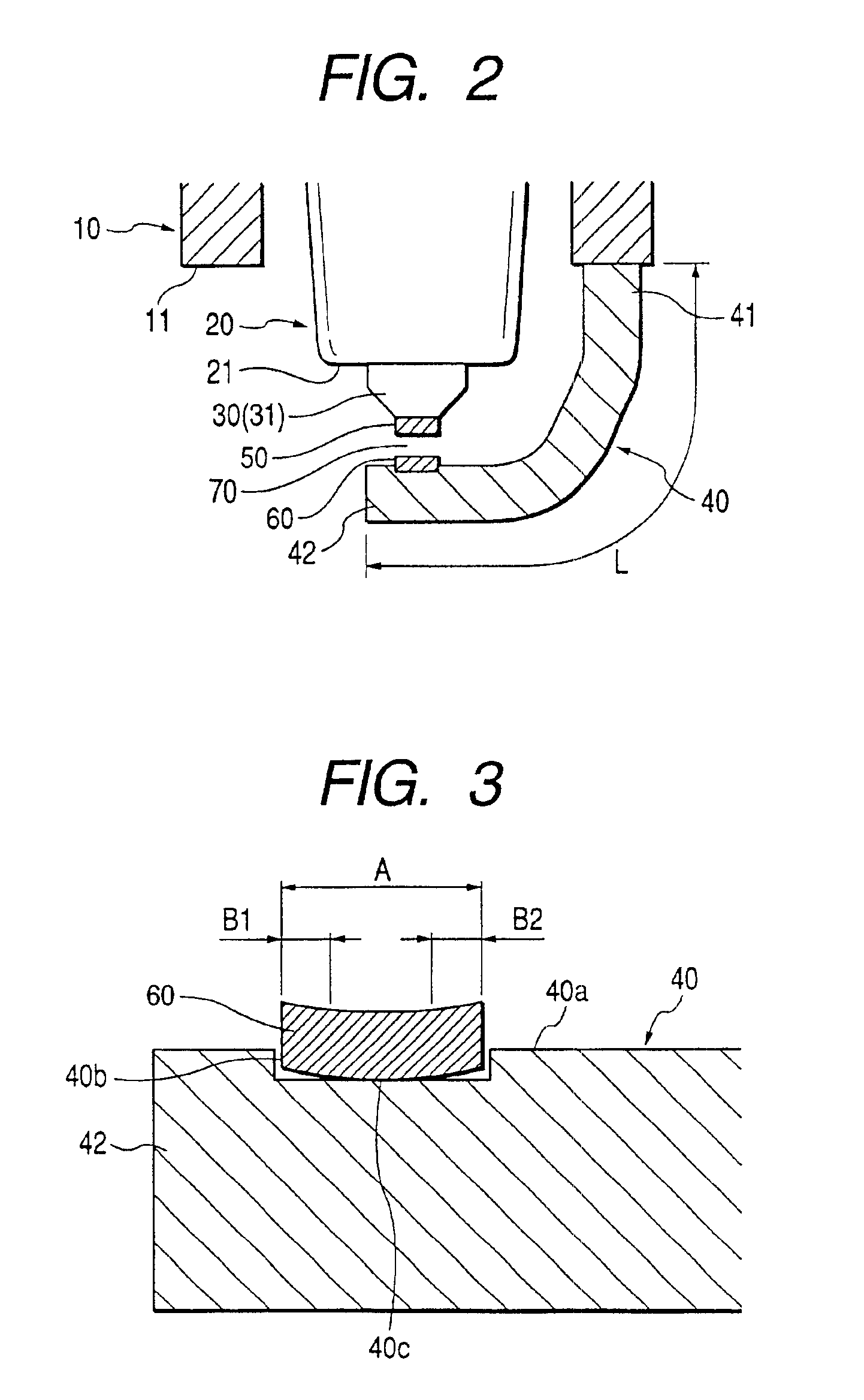
[0082]A preferred embodiment of the present invention will be explained hereinafter with reference to the attached drawings. FIG. 1 is a half crosssectional view showing an overall arrangement of a spark plug S1 in accordance with a preferable embodiment of the present invention. FIG. 2 is an enlarged view showing a spark discharge portion of the spark plug S1.

[0083]The spark plug S1 is applicable to an ignition device of an automotive engine and is fixedly inserted into a screw hole opened in an engine head (not shown) defining a combustion chamber of the engine.

[0084]The spark plug S1 has a cylindrical metallic housing 10 which is made of an electrically conductive steel member (e.g., low carbon steel). The metallic housing 10 has a threaded portion 10a for securely fixing the spar...


PUM

PropertyMeasurementUnit
weight %aaaaaaaaaa
weight %aaaaaaaaaa
weight %aaaaaaaaaa

Abstract

Noble metallic tips, made of a Pt alloy or an Ir alloy, are fixed to electrode base materials. The electrode base materials are an alloy containing a chief element selected from the group consisting of Ni, Fe, and Co and a plurality of additive elements. At least two kinds of additive elements contained in this alloy have a standard free energy of formation smaller than that of the chief element.

Description

BACKGROUND OF THE INVENTION[0001]This invention relates to a spark plug having a center electrode, a ground electrode, and a noble metallic tip fixed to an electrode base material serving as at least one of the center electrode and the ground electrode. The spark plug of this invention is preferably applicable to an internal combustion engine installed in an automotive vehicle, a cogeneration system, and a pressurized gas feeding pump, or the like.[0002]Generally, a spark plug used for an internal combustion engine has a center electrode, an insulator for holding this center electrode, a housing for fixedly holding this insulator, and a ground electrode having a proximal portion fixed to the housing and a distal portion opposing the center electrode. To meet the high performance of recent engines or to realize a maintenance free, assuring long life of spark plug is earnestly required nowadays. To this end, a noble metallic tip is fixed to each apical end (i.e., a spark discharge por...

Claims


Application Information

Patent Timeline
Patent Type & Authority Patents(United States)
IPC IPC(8): H01T21/02H01T13/39H01T21/00H01T13/20
CPCH01T21/02H01T13/39H01T13/20
Inventor KANAO, KEIJIHORI, TSUNENOBU
Owner DENSO CORP
Learn More