Earth boring apparatus and method offering improved gage trimmer protection

a technology of earth boring and protection, applied in the direction of drilling rods, drilling pipes, cutting machines, etc., can solve the problems of reducing the protection ability affecting the performance reducing the protection capacity of the gage trimmer, so as to reduce the risk of impact loading, impede impact loading, and reduce wear resistance

Inactive Publication Date: 2005-04-26
BAKER HUGHES INC
View PDF12 Cites 135 Cited by
  • Summary
  • Abstract
  • Description
  • Claims
  • Application Information

AI Technical Summary

Benefits of technology

[0013]The present invention comprises a drilling tool having at least one gage trimmer and at least one protective structure placed proximate to a leading edge and a trailing edge of the at least one gage trimmer. More specifically, at least one protective structure is placed proximate to the leading and trailing edges of at least one gage trimmer so as to protrude or extend from the gage profile to an extent substantially equal to the exposure of the at least one gage trimmer in order to protect the at least one gage trimmer. In such a configuration, a protective structure proximate to the leading and trailing edges of a gage trimmer will contact the formation generally when the gage trimmer comes into contact with the formation along the wall of the formation. Particularly, when the gage of the bit encounters impact with the borehole or casing, the protective structure(s) engage the formation material, thus preventing damage to the gage trimmer and extending bit life. In addition, a protective structure may be configured with a contact area for contacting a borehole or casing that may be larger than the surface of the gage trimmer that may contact a borehole or casing. Further, if the drill bit is rotated within a casing or borehole without drilling, the protective structure(s) substantially limit the ability of the gage trimmer to engage or become damaged by contact with the inner diameter of the casing or borehole.
[0014]Protective structures are less wear resistant than a superabrasive material layer of the gage trimmer. Thus, the protective structures do not greatly impede the cutting function of the gage trimmer during drilling, as the protective structures relatively quickly wear down, leaving the gage trimmers exposed for cutting. However, during unstable motion of the drill bit, i.e., whirling or when the drill bit is rotated inside the casing, the gage trimmers may experience impact loading. Protective structures according to the present invention may impede such impact loading from damaging the gage trimmers.
[0018]As noted hereinabove, protective structures of the present invention may be sized and positioned to have substantially the same exposure as their respective gage trimmers. This may be advantageous because the protective structure(s) thereby prevent impact loading because the protective structure(s) make contact with the borehole or other surface at substantially the same exposure as the gage trimmer. Upon wearing, the protective structure(s) may maintain substantially the same exposure as the gage trimmer, or may have only slightly less than the exposure of the gage trimmer. Stated another way, although the protective structure(s) have much less wear resistance than the superabrasive layer of the gage trimmer and therefore do not substantially impede the gage trimmer from engaging the formation, the protective structure wear may be determined, to a large extent, by the wear of the gage trimmer because if the protective structure is less exposed than the gage trimmer, the gage trimmer will prevent further wear of the protective structure as it will be cutting a diameter greater than the exposure of the protective structure. As the gage trimmer wears at a slow rate, the protective structure(s) may be exposed to the formation and may be worn to substantially the same or a slightly lesser exposure. Thus, upon installation and subsequent grinding (if required), the gage trimmer and its associated protective structure(s) may be substantially equally exposed and may remain substantially equally exposed or slightly less exposed during continued use. Additionally, gage trimmers and associated protective structure(s) may be replaced and ground (if necessary) to a common exposure.

Problems solved by technology

Further, if the drill bit is rotated within a casing or borehole without drilling, the protective structure(s) substantially limit the ability of the gage trimmer to engage or become damaged by contact with the inner diameter of the casing or borehole.
Thus, the protective structures do not greatly impede the cutting function of the gage trimmer during drilling, as the protective structures relatively quickly wear down, leaving the gage trimmers exposed for cutting.
However, during unstable motion of the drill bit, i.e., whirling or when the drill bit is rotated inside the casing, the gage trimmers may experience impact loading.

Method used


Image

  • Earth boring apparatus and method offering improved gage trimmer protection
  • Earth boring apparatus and method offering improved gage trimmer protection
  • Earth boring apparatus and method offering improved gage trimmer protection

Examples


Embodiment Construction

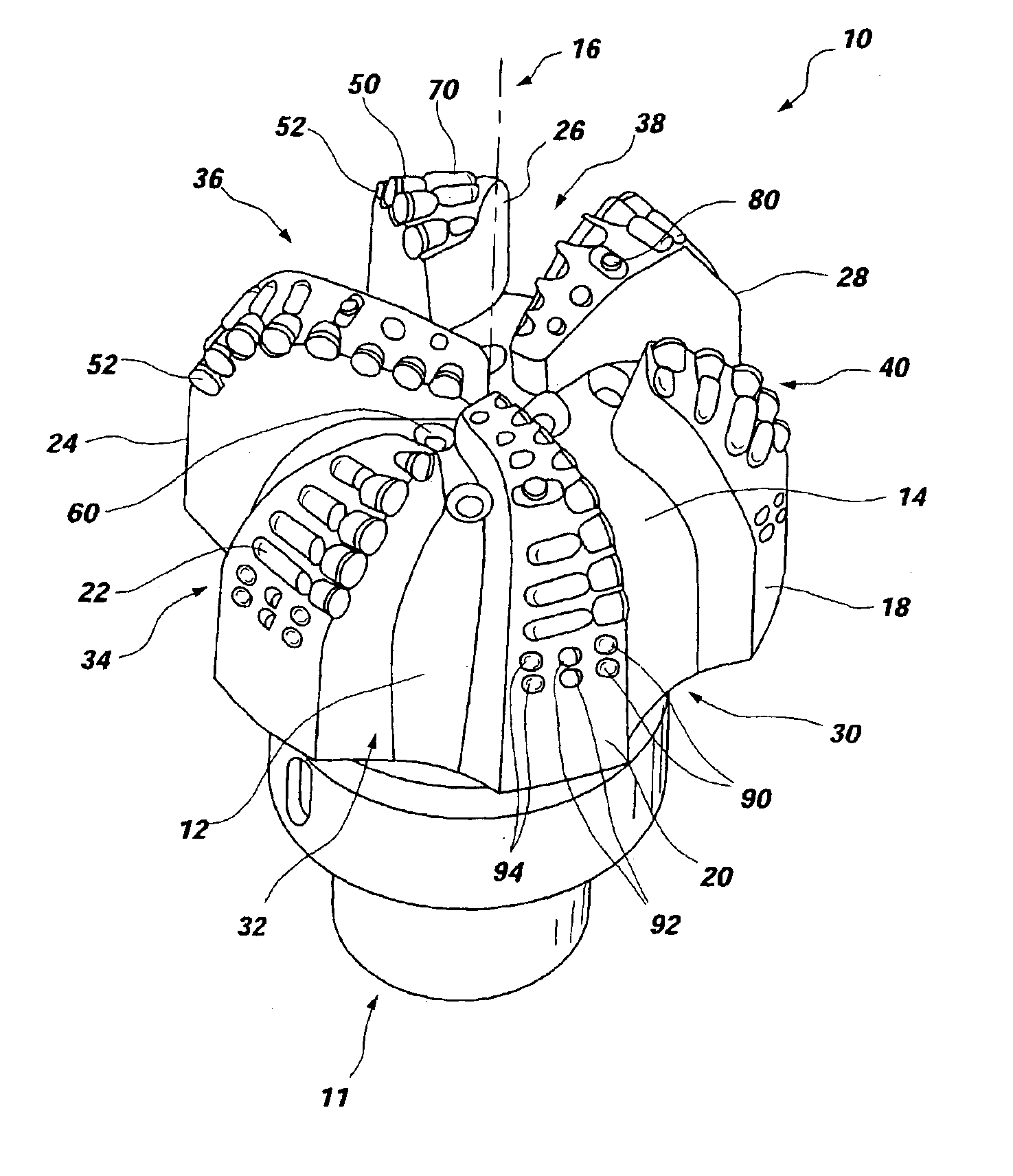
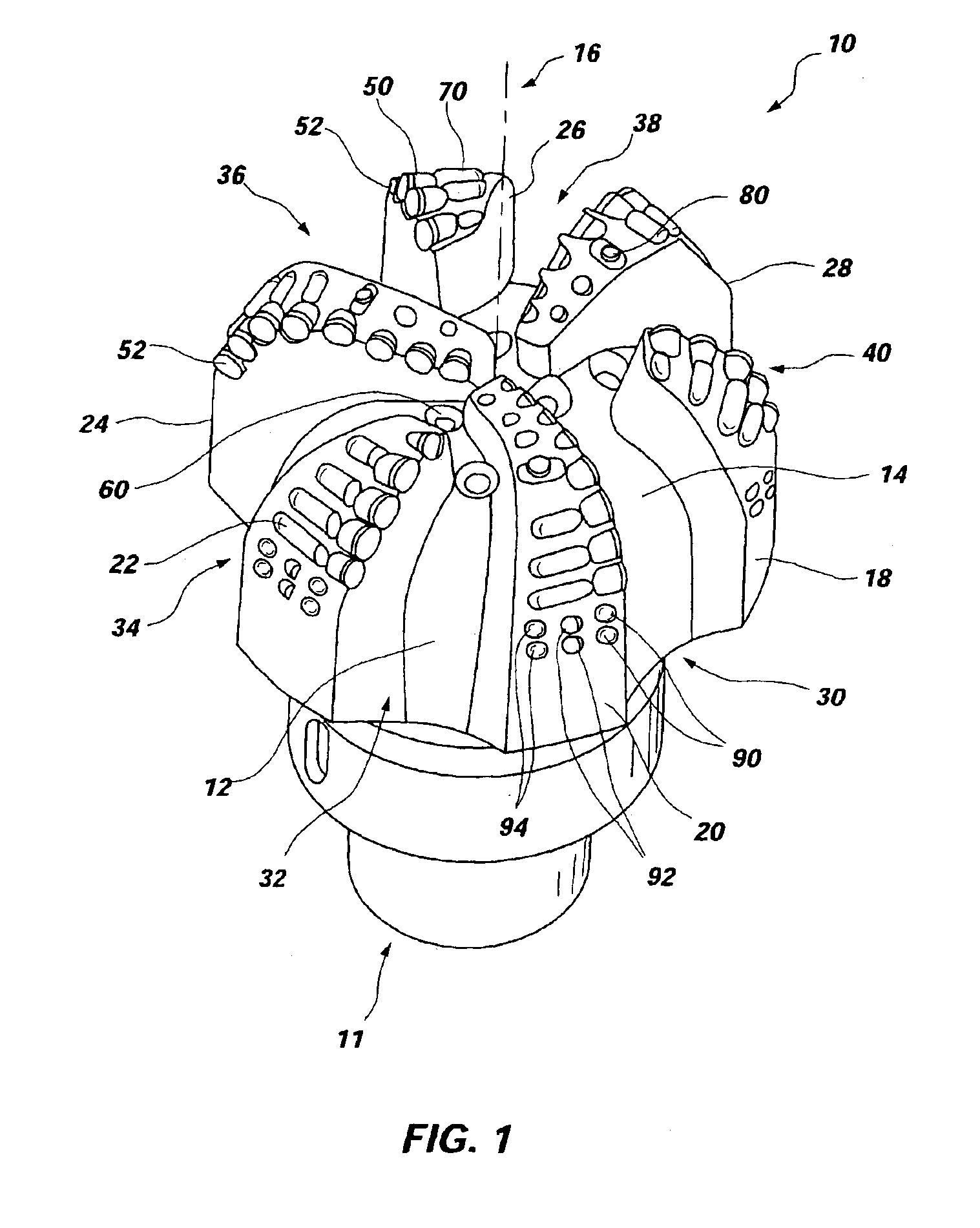
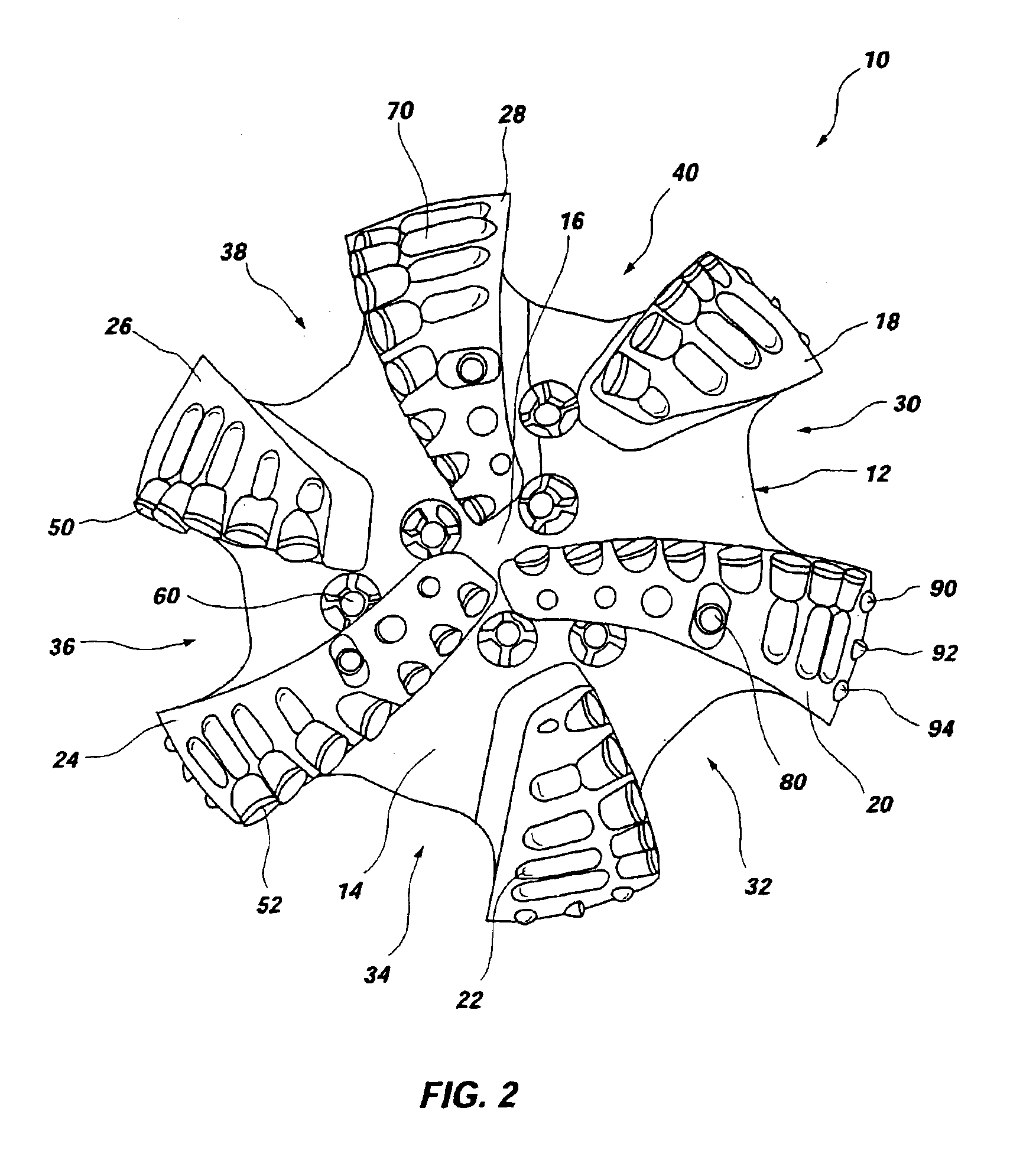
[0037]Referring to FIGS. 1 and 2 of the drawings, a rotary drag bit 10 of the present invention is illustrated. Rotary drag bit 10 includes a body 12 having a face 14 radially extending outward from the centerline or longitudinal axis 16 of the bit body 12. Six blades comprising primary blades 20, 24, and 28 as well as secondary blades 18, 22, and 26 respectively extend over and above face 14 and radially outwardly therebeyond, defining six longitudinally extending junk slots 30, 32, 34, 36, 38, and 40 therebetween. The terms “primary” and “secondary” are employed with regard to the relative volumes of rock cut by the cutter groups of the various blades. A plurality of superabrasive cutters 50, preferably PDCs, may be mounted to each blade 18 through 28 with their cutting faces 52 facing generally in the direction of bit rotation. Wear knots 70 follow many of the cutters shown, positioned distal to the cutting face 52 of each respective cutter 50. In addition, secondary cutters 80, ...


PUM


Abstract

A rotary drill bit for drilling subterranean formations configured with at least one protective structure proximate to the rotationally leading and trailing edges of a gage trimmer, wherein the at least one protective structure is positioned at substantially the same exposure as its associated gage trimmer. Particularly, the apparatus of the present invention may provide protection for gage trimmers during drilling, tripping, and / or rotation within a casing; i.e., when changing a drilling fluid. Protective structures may be configured and located according to anticipated drilling conditions including helix angles. In addition, a protective structure may be proximate to more than one gage trimmer while having a substantially equal exposure to each associated gage trimmer. Methods of use and a method of rotary bit design are also disclosed.

Description

BACKGROUND OF THE INVENTION[0001]1. Field of the Invention[0002]The present invention relates generally to drilling a subterranean borehole and, more specifically, to protecting gage trimmers located adjacent to the gage of a drill bit by way of protective structures. The method and apparatus of the present invention may effect such protection for gage trimmers during drilling and / or during rotation within a casing, i.e., when changing a drilling fluid.[0003]2. State of the Art[0004]Fixed cutter rotary drill bits for drilling oil, gas, and geothermal wells, and other similar uses typically comprise a solid metal or composite matrix metal body having a lower cutting face region and an upper shank region for connection to the bottom hole assembly of a drill string formed of conventional jointed tubular members, which are then rotated as a single unit by a rotary table, top drive, drilling rig, or downhole motor, alone or in combination with one another. Alternatively, rotary drill bit...

Claims


Application Information

Patent Timeline
IPC IPC(8): E21B17/00E21B17/10E21B10/46E21B10/54E21B10/55
CPCE21B10/46E21B17/1092E21B10/55
Inventor MCCORMICK, RONNY D.BALL, MUMTAZANDERSON, MARK E.DYKSTRA, MARK W.DOSTER, MICHAEL L.ISBELL, MATTHEW R.
Owner BAKER HUGHES INC
Why Eureka
Try Eureka