
Wear Resistant Granular Direction Altering Device

a technology of granular direction and change device, which is applied in the direction of transportation and packaging, manufacturing tools, and so on, can solve the problems of high cost of wear-resistant steel and can be extremely difficult to bend, and achieve the effect of less wear resistance and extension of the useful life of the agricultural product delivery applicator

Active Publication Date: 2021-09-23
BLUE LEAF I P INC
View PDF0 Cites 1 Cited by
  • Summary
  • Abstract
  • Description
  • Claims
  • Application Information

AI Technical Summary

Benefits of technology

This patent provides a system for delivering agricultural products using a pneumatic conveying system with reinforced supply lines. The reinforcement can be done by using wear-resistant materials on at least portions of the supply lines. The system can also include segmented elbows and welded-in filler metal lines to create a layer of wear-resistant steel over the base metal of the supply line. These improvements help extend the lifespan of the applicator and minimize impacts and abrasions from particulate matter during delivery.

Problems solved by technology

However, wear-resistant steel is expensive and can be extremely difficult to bend.

Method used


Image

  • Wear Resistant Granular Direction Altering Device
  • Wear Resistant Granular Direction Altering Device
  • Wear Resistant Granular Direction Altering Device

Examples


first embodiment

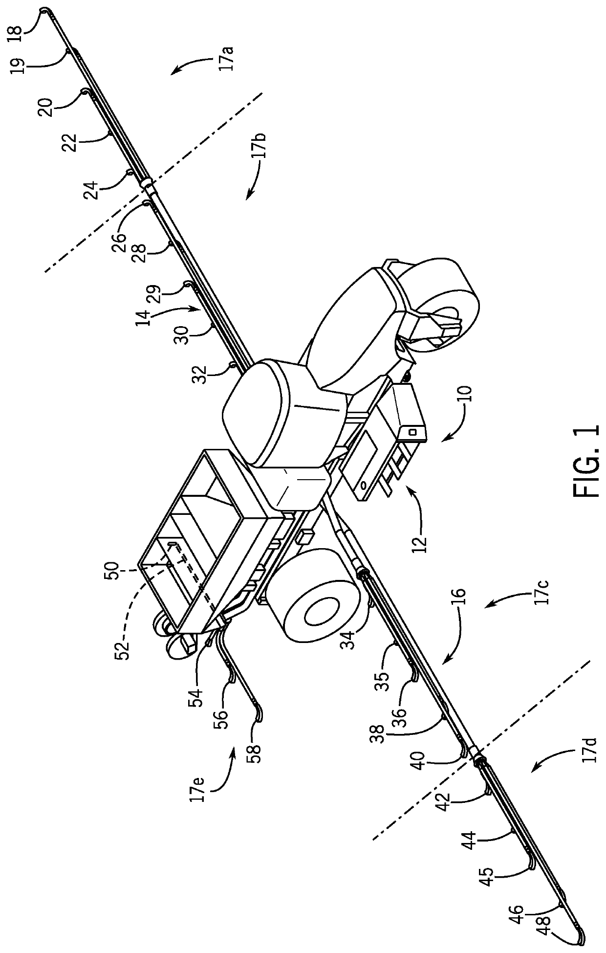
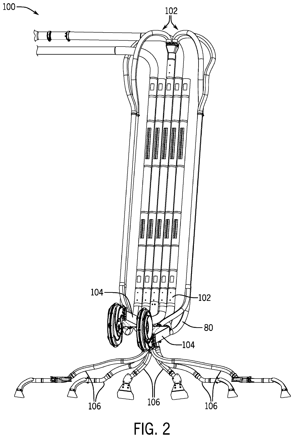
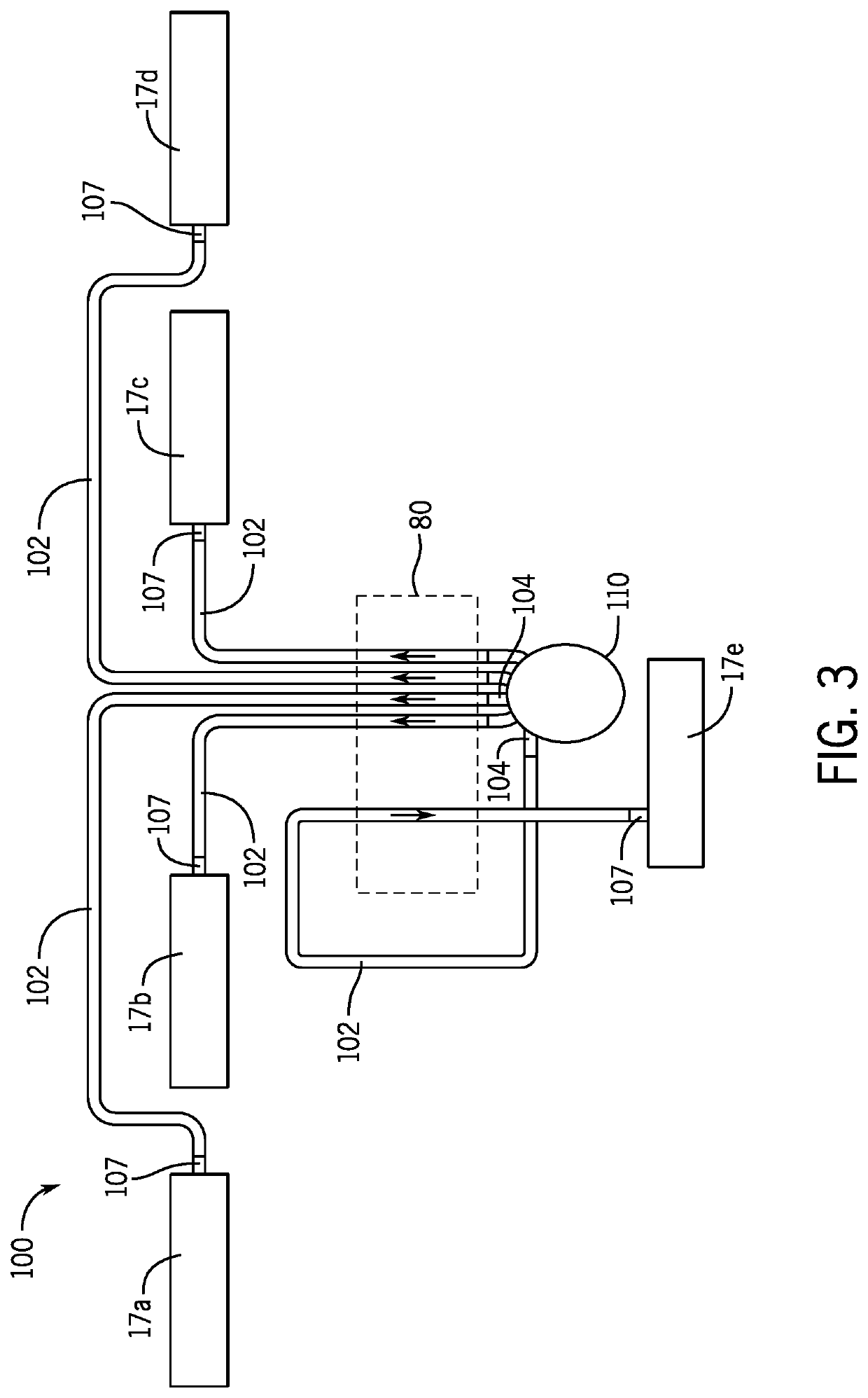
[0024]In one embodiment, the large diameter supply lines 102 or secondary supply lines 106 may be reinforced by using at least one different material or at least one additional material. For example, in a first embodiment, a wear-resistant ferrous material such as an abrasion-resistant steel may be used to form at least part of the large diameter supply line 102 and / or secondary supply line 106. The abrasion-resistant steel material may have a hardness value of at least about 300 HBW (Brinell Hardness), typically a hardness value of at least about 400 HBW, with a hardness value of at least 450 being the most typical. Other or additional materials are envisioned and foreseeable in alternative embodiments. Although wear-resistant steel tubes or pipes can extend the useful lifespan of the agricultural application implement 10, wear-resistant steel pipes may be the wrong shape or size to be used as part of the supply line 102. Thus, the wear-resistant steel pipes may have to be customiz...

second embodiment

[0028]In a second embodiment, the supply lines 102, 106 may be made from a relatively less hard material that is reinforced through hard surface welding. As illustrated in FIG. 6, a filler metal or alloy as a consumable weld electrode is used to reinforce the supply line 102 by building up a welded surface to a base metal (not shown) of an inner circumference of the supply line 102 to provide both impact and abrasion resistance to that region of the supply line 102. In one embodiment, wear-resistant steel may be used as the filler metal. However, other materials are envisioned and foreseeable. An arm (not shown) of, for example, a robotic or other automated welding machine extends into the supply line 102 and lays down continuous substantially parallel filler metal lines 180 to form a layer of wear-resistant steel on the inner region of the supply line 102, as shown in FIG. 6. The filler metal lines 180 may be formed by a welding procedure, such as SMAW (shielded metal arch welding)...


PUM

PropertyMeasurementUnit
diameteraaaaaaaaaa
diameteraaaaaaaaaa
diameteraaaaaaaaaa

Abstract

The invention provides a pneumatic conveying system having a series of supply lines with at least portions of the lines being wear resistant to extend the useful lifespan of an agricultural product delivery applicator. The wear resistant supply line(s) may be made from a hard material and have a curve(s) defined by angled or mitered segments that are welded or otherwise joined to collectively provide the curve(s) The wear resistant supply lines may be at least partially reinforced by way of, for example, welded or other build up wear resistant material(s) at high wear zones of the supply lines.

Description

FIELD OF THE INVENTION[0001]The invention relates generally to an agricultural product delivery system for applying particulate material such as seed, fertilizer, herbicide, or insecticide to a field, and more particularly an agricultural product delivery applicator with a pneumatic conveying system having a series of at least partially reinforced supply lines that provide wear resistance to high wear zones of the lines.BACKGROUND OF THE INVENTION[0002]Agricultural product delivery applicators (or systems) are known to utilize various mechanisms, including mechanical and pneumatic systems, to assist in the movement and delivery of particulate material or product. Example product that can be delivered include fertilizer, seed, insecticide, or herbicide. The product can move from a product bin through an interior passage provided by a series of elongate tubes or pipes, which extend from the product supply chamber to a product applicator. The applicator places the product on or in grow...

Claims


Application Information

Patent Timeline
Patent Type & Authority Applications(United States)
IPC IPC(8): B65G53/52B65G53/04B23K31/02B23K35/24B23K9/04B23K9/028B05B7/14A01C7/08A01M9/00A01C15/00
CPCB65G53/523B65G53/04B23K31/027B23K35/24B23K9/044B23K9/0284B23K2101/06B05B7/1486A01C7/084A01M9/003A01C15/00B65G2207/48B23K9/0282A01C7/081A01C15/04B23K9/048B23K2103/04
Inventor RUPPERT, REX LEROYHONERMANN, JOHN PAUL
Owner BLUE LEAF I P INC
Learn More