Friction pull plug welding: chamfered heat sink pull plug design

a technology of friction pull plugs and heat sinks, which is applied in the direction of welding devices, soldering devices, manufacturing tools, etc., can solve the problems of complex bonding of the last interfacial location, affecting the welding process, and reducing the welding efficiency of the plug top, so as to facilitate a good weld and increase the heating capacity of the welding process. , the effect of less heat sinks

Inactive Publication Date: 2005-04-19
LOCKHEED MARTIN CORP
View PDF27 Cites 31 Cited by
  • Summary
  • Abstract
  • Description
  • Claims
  • Application Information

AI Technical Summary

Benefits of technology

[0018]The apparatus of the present invention solves the problems confronted in the art in a simple and straightforward manner. What is provided is an apparatus for and a method of friction plug welding an article using a plug that has a geometry that provides less heat sink and facilitates a good weld when the plug is pulled. As demonstrated through several single variable experiments, a larger plug mass acting as a heat sink at the top of the weld has deleterious affects on the bonding of the plug top. Thermodynamically, plug mass acts to conduct heat away from the interface, while the atmosphere insulates the interface, increasing the heating capabilities of the welding process. With less plug mass, or heat sink, left on top of the plate surface after the completion of a weld, the heat produced by the weld process is not conducted away from the interface as rapidly.
[0029]The plug is pulled while spun by the motor. Preferably the plug is pulled also after the spinning stops, with a load the same as or different from the load while spinning. After the spinning has taken place and the plug is welded in place, the excess part of the plug is cut off and the weld machined down to make it smooth. Pulling a tapered plug during plug welding allows all equipment, including a backing plate, to be on one side of the article being welded. Pull welding eliminates the need for large backing structures that must react high loads associated with friction plug push welding, often exceeding 10,000 pounds force, while at the same loads deflect an amount often less than 0.25 inches. A hydraulically powered direct drive weld has been used; however, an electrically powered direct drive, or inertia drive flywheel weld system may also be used.
[0030]The inventors have found that satisfactory welds occur most frequently when the plug diameter is large enough to maintain a mechanically stable cool core. For this reason, plug diameters have continued to increase, and more powerful weld equipment has been acquired. Techniques have been developed to weld larger diameter plugs while minimizing the required motor power. One such finding entails varying the axial stroke rate during the weld process to decrease the initial contact friction. In this process, it is preferable for the plug and article to contact slowly, thereby reducing the rotational friction at contact. After the boundary between the plug and article plasticizes, then it is preferable, although not required, to increase the stroke rate, thereby increasing the rate of heating at the interface to achieve weld temperatures. This discovery significantly reduces the required power to perform welds, and is advantageous in performing large welds whose power requirement exceeds that which the system is designed to deliver.
[0034]Experimental data has shown that the mass of plug heat sink remaining above the top of the plate surface after a weld is completed (the plug heat sink) affects the bonding at the plug top. A minimized heat sink ensures complete bonding of the plug to the plate at the plug top. However, with a minimal heat sink three major problems can arise, the entire plug could be pulled through the plate hole, the central portion of the plug could be separated along grain boundaries, or the plug top hat can be separated from the body. The Chamfered Heat Sink Pull Plug Design allows for complete bonding along the inside skin line (ISL) interface through an outside diameter minimal mass heat sink, while maintaining enough central mass in the plug to prevent plug pull through, central separation, and plug top hat separation.
[0035]A larger plug mass acting as a heat sink at the top of the weld has deleterious affects on the bonding of the plug top. Thermodynamically, plug mass acts to conduct heat away from the interface, while the atmosphere insulates the interface, increasing the heating capabilities of the welding process. With less plug mass, or heat sink, left on top of the plate surface after the completion of a weld, the heat produced by the weld process is not conducted away from the interface as rapidly.

Problems solved by technology

As demonstrated through several single variable experiments, a larger plug mass acting as a heat sink at the top of the weld has deleterious affects on the bonding of the plug top.
This situation poses a problem to ensuring complete plug / plate interfacial bonding at the top of the weld, the last location of bonding during the welding process.
The problem of bonding this last interfacial location is quite complex, involving a combination of both loading and heat flow.
However, three major problems can arise from a minimized heat sink, the entire plug could be pulled through the plate hole, the central portion of the plug could be separated along grain boundaries, or with a top hat plug, the plug top hat can be separated from the body.
Each of these conditions is completely unacceptable for a production acceptable process.

Method used


Image

  • Friction pull plug welding: chamfered heat sink pull plug design
  • Friction pull plug welding: chamfered heat sink pull plug design
  • Friction pull plug welding: chamfered heat sink pull plug design

Examples


Embodiment Construction

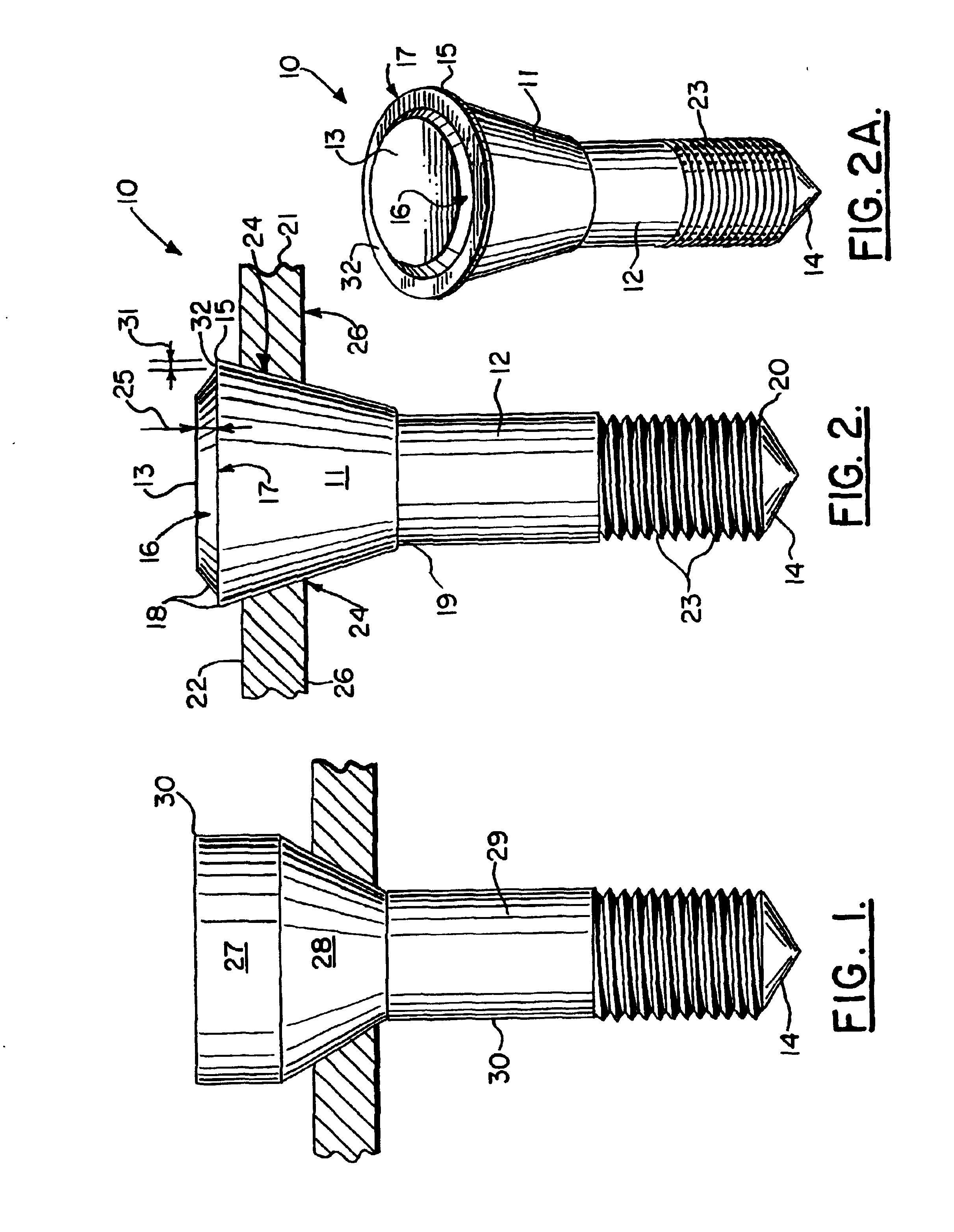
[0053]FIG. 1 shows a pull plug 30 with a large heat sink mass, showing areas of hot interface and cold material when the plug 30 is pulled and rotated to produce heating and forging load. Pull plug 30 has frustoconical section 28 and shank 29 below heat sink mass 27. Such a large heat sink mass 27 can cause problems as will be discussed more fully hereinafter.

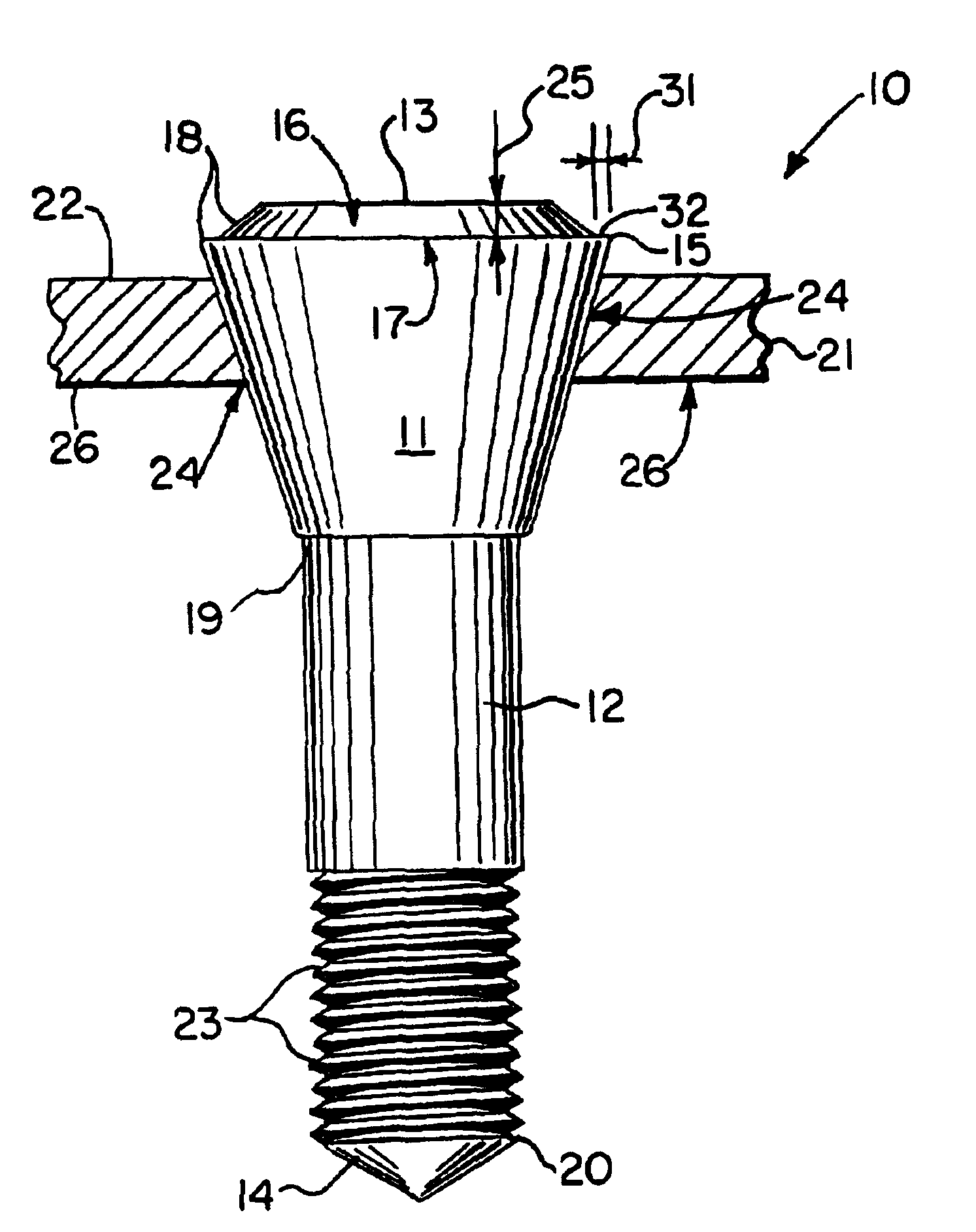
[0054]In FIGS. 2-2A, the first embodiment of the apparatus of the present invention is designated generally by the numeral 10. FIGS. 2-2A illustrate a diagram wherein a pull plug 10 has been placed in position through an opening (e.g. drilled) 24 in plate 21. Plug 10 has an upper portion 18 and a lower portion 20. Plate section 21 provides upper surface 22 and lower surface 26. Upper portion 18 of plug 10 includes heat sink 13 and frustoconical section 11 that occupies opening 24. Plug 10 lower end portion 20 includes shank 12, and tip 14.

[0055]The shank 12 can have a threaded section 23 enabling connection to a rotary tool, dr...


PUM

PropertyMeasurementUnit
lengthaaaaaaaaaa
diameteraaaaaaaaaa
radial distanceaaaaaaaaaa

Abstract

The average strength of a pull plug weld is increased and weak bonding eliminated by providing a dual included angle at the top one third of the pull plug. Plugs using the included angle of the present invention had consistent high strength, no weak bonds and were substantially defect free. The dual angle of the pull plug body increases the heat and pressure of the weld in the region of the top one third of the plug. This allows the plug to form a tight high quality solid state bond. The dual angle was found to be successful in elimination of defects on both small and large plugs.

Description

CROSS-REFERENCE TO RELATED APPLICATIONS[0001]This is a continuation-in-part of U.S. patent application Ser. No. 09 / 562,257, incorporated herein by reference, filed 2 May 2000, now U.S. Pat. No. 6,460,750.[0002]This is also a continuation-in-part of U.S. patent application Ser. No. 09 / 858,191, incorporated herein by reference, filed 15 May 2001 now ABN, which is a continuation-in-part of U.S. patent application Ser. No. 09 / 547,800, filed 11 Apr. 2000, now U.S. Pat. No. 6,230,958.[0003]Priority of U.S. Provisional Patent Application Ser. No. 60 / 160,131, filed Oct. 18, 1999, incorporated herein by reference, is hereby claimed.[0004]The assignee is the owner of U.S. Pat. No. 6,213,379 entitled “Friction Plug Welding,” and incorporated herein by reference. For parameters not mentioned herein, see U.S. Pat. No. 6,213,379.[0005]Also incorporated herein by reference are U.S. Pat. Nos. 6,386,419 and 6,253,987.STATEMENT REGARDING FEDERALLY SPONSORED RESEARCH OR DEVELOPMENT[0006]The invention ...

Claims


Application Information

Patent Timeline
Patent Type & Authority Patents(United States)
IPC IPC(8): B23K20/12
CPCB23K20/1295B23K20/129
Inventor COLETTA, EDMOND R.CANTRELL, MARK A.
Owner LOCKHEED MARTIN CORP
Why Eureka
Try Eureka