Floating fountain devices and systems

a technology of floating fountains and devices, applied in dental surgery, lighting and heating apparatus, combustion types, etc., can solve the problems of difficult maintenance, difficult installation and maintenance of known floating fountains, and replacement of entire electrical cables, so as to achieve no rotational tendencies and improve stability.

Inactive Publication Date: 2005-04-12
FOSTER RICHARD S
View PDF25 Cites 5 Cited by
  • Summary
  • Abstract
  • Description
  • Claims
  • Application Information

AI Technical Summary

Benefits of technology

This invention separately provides floating fountain d...

Problems solved by technology

Unfortunately, known floating fountains are expensive and difficult to install and maintain.
If the integrity of this electrical cable becomes compromised, due to corrosion, age, or destruction by animals, the entire electrical cable must be replaced.
Furthermore, due to the rotation of components within the pump motor, it is often difficult to maintain the desired positioning of a floating fountain in a lake.
Once the floating fountai...

Method used


Image

  • Floating fountain devices and systems
  • Floating fountain devices and systems
  • Floating fountain devices and systems

Examples


Embodiment Construction

For simplicity and clarification, the design factors and layout of the floating fountain devices and systems according to this invention are explained with reference to several exemplary embodiments of a floating fountain according to this invention. The basic explanation of the floating fountain is applicable for the understanding and design of the constituent components employed in the floating fountain devices and systems of this invention.

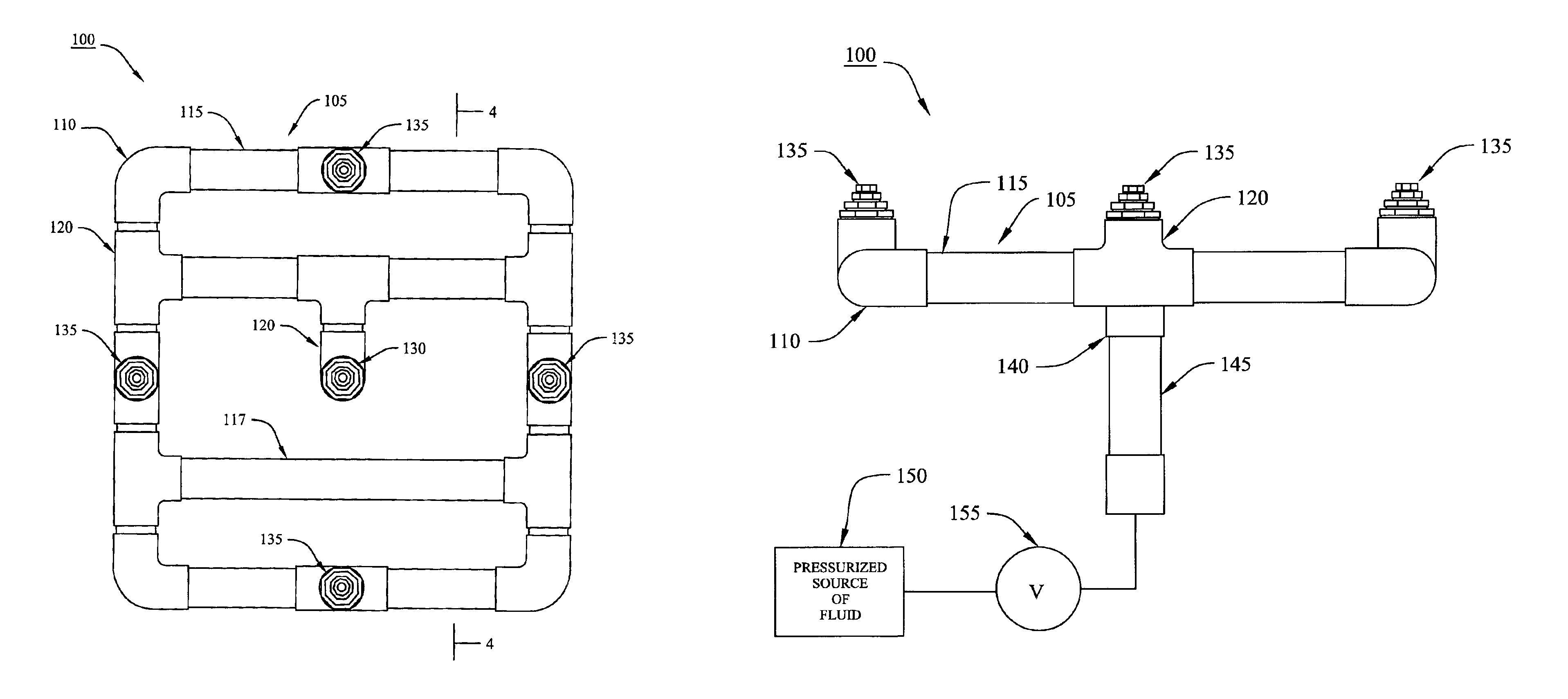
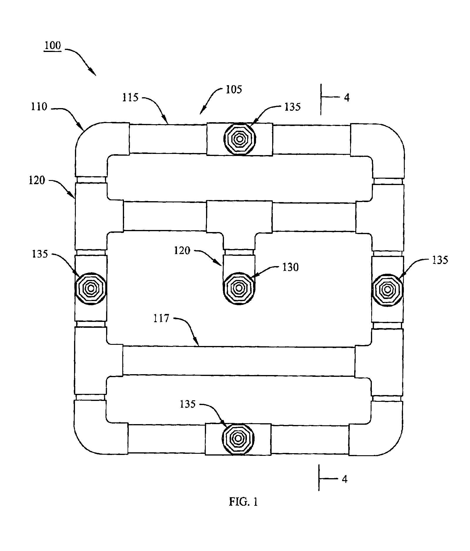
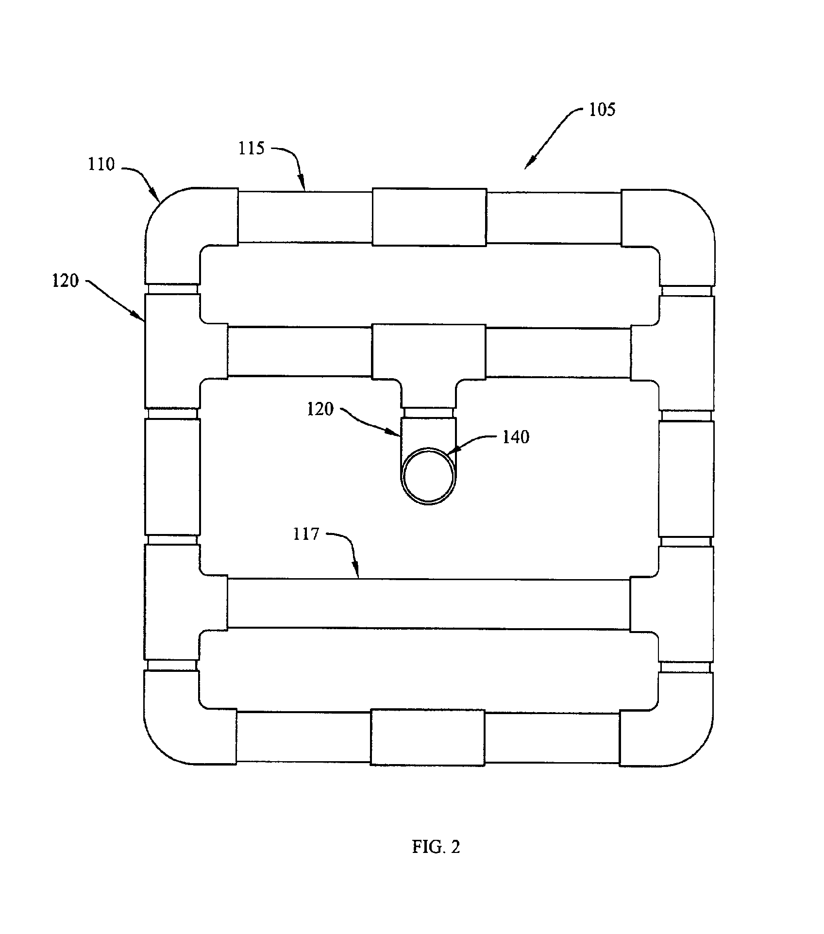
FIGS. 1 through 3 show a top, a bottom, and a side view, respectively, of a first exemplary embodiment of a floating fountain 100 according to this invention. FIG. 4 shows a schematic cross-sectional view taken along line 4—4 of the first exemplary embodiment of the floating fountain 100 of FIG. 1. As shown in FIGS. 1 through 4, the floating fountain 100 comprises a base assembly 105, a primary nozzle member 130, at least one secondary nozzle member 135, and a connection member 140. Each of these elements is disposed in a communicating relation...


PUM


Abstract

A floating fountain that includes of a tubular, hollow base assembly that can be connected to a pressurized source of fluid, a primary nozzle member located centrally to the base assembly, and a plurality of secondary nozzle members located on the base assembly. Each nozzle member is connected to the base assembly such that pressurized fluid may be communicated from the base assembly to the primary nozzle member and the secondary nozzle members in a manner that allows the pressurized fluid to be organized into separate streams of fluid, which extend from each respective nozzle member. A float body is affixed to a bottom side of the base assembly to provide buoyancy to the floating fountain device. Additionally, an infinitely variable valve is included between the pressurized source of fluid and the base assembly so that the pressure at which the pressurized fluid enters the base assembly and is provided to each nozzle member may be variably controlled.

Description

BACKGROUND OF THE INVENTION1. Field of the InventionThis invention relates generally to floating fountains.2. Description of Related ArtGenerally, water fountains are considered to be esthetically pleasing, and are often seen as part of the landscaping in housing communities, golf courses, parks, resorts, and the like. Floating fountains not only bring beauty to a well-landscaped area, but also provide aeration to lakes and ponds. While creating an attractive spray display, floating fountains aerate the water in the lake or pond in which they are situated by adding movement and oxygen to the water.Known floating fountains typically consist of a float with a pump motor suspended below it. The float is generally held in position in a lake by shoreline ropes or ropes anchored to, for example, concrete blocks at the bottom of the lake. The input to the pump is submerged below the surface of the water and the output of the pump typically includes a nozzle, which allows an output stream o...

Claims


Application Information

Patent Timeline
IPC IPC(8): B05B17/00B05B17/08
CPCB05B17/08
Inventor FOSTER, RICHARD S.
Owner FOSTER RICHARD S
Why Eureka
Try Eureka