Machine tool and method for machining a rod-shaped workpiece

a technology of a machine tool and a workpiece, which is applied in the direction of turning equipment, milling equipment, large fixed members, etc., can solve the problems of inability to automate with difficulty and considerable design outlay, and achieve the effect of reducing the overall design of the machine tool, facilitating and facilitating the machining of rod-shaped workpieces, and reducing the cost of machining

Inactive Publication Date: 2005-04-05
CHIRON WERKE
View PDF15 Cites 12 Cited by
  • Summary
  • Abstract
  • Description
  • Claims
  • Application Information

AI Technical Summary

Benefits of technology

It is an object of the present invention to simplify the overall design of the machine tool mentioned at the beginning. It is another object to provide a machine tool that easily allows to machine the clamping point at which the workpiece is accommodated in the first holder by means of a tool accommodated in the tool spindle. A further object of the invention is to provide a machine tool that allows a precise machining of a workpiece at its clamping point at which the workpiece is accommodated in the first holder. Another object is to provide a method for easy and precise machining of rod-shaped workpieces at several surfaces.
Owing to a small distance between tool carrier and swivel axis, the tool moves on a circular path of small radius during the swiveling of the tool spindle, a factor which leads to short compensating movements of the traveling column if only the angular position of the tool, but not its spatial position as such, is to be varied. Together with the arrangement of swivel axis and spindle axis in such a way that they do not intersect, short traverse paths of the traveling column in the direction perpendicularly to the longitudinal axis of the workpiece and to the swivel axis can also be realized. In traveling-column machines in the conventional style, in which both the workpieces and the swivel axis are arranged horizontally, the traverse paths in the vertical are shortened by this measure. Consequently, such a machine tool requires a small amount of space in the vertical; the “Z-axis” can therefore be designed with a short stroke.

Problems solved by technology

This operation is relatively time-consuming and could hitherto only be automated with difficulty and with considerable design outlay.

Method used


Image

  • Machine tool and method for machining a rod-shaped workpiece
  • Machine tool and method for machining a rod-shaped workpiece
  • Machine tool and method for machining a rod-shaped workpiece

Examples


Embodiment Construction

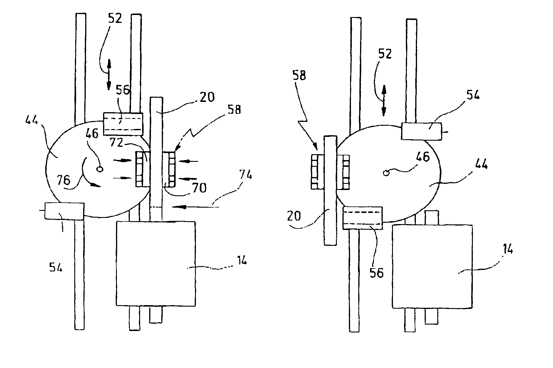
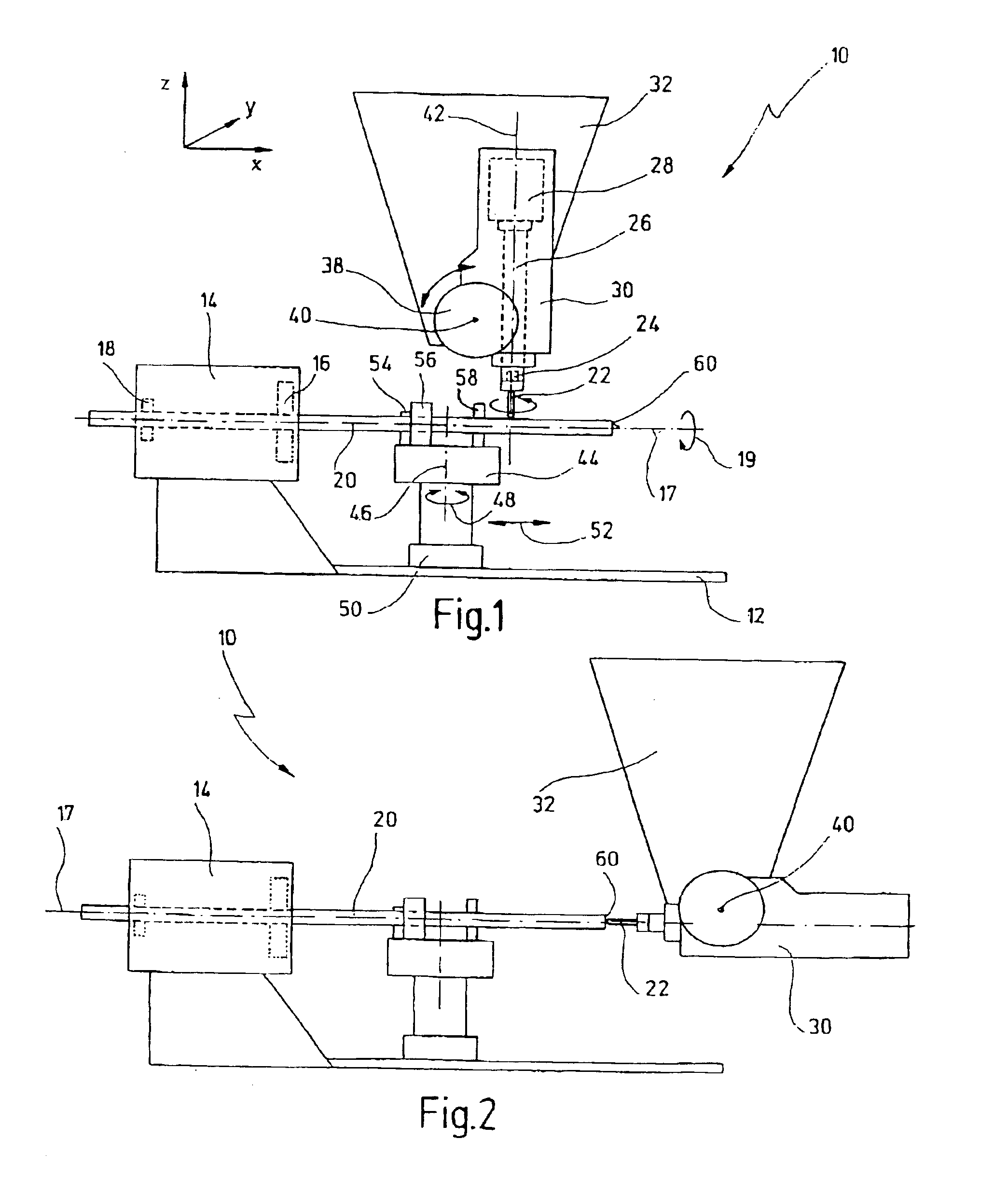
In a schematic simplified representation, FIG. 1 shows some subassemblies of a new machine tool, this machine tool being designated overall by 10 and being designed as a traveling-column machine. Fastened to a machine bed 12 is an NC lathe spindle 14, in which chuck jaws 16 and a shaft encoder 18 connected to a control (not shown) of the machine tool are only indicated schematically. By means of the NC lathe spindle 14, a rod-shaped workpiece 20 clamped in the chuck jaws 16 can be set in rotation about a longitudinal axis (indicated by 17), as indicated in FIG. 1 by an arrow 19. In this case, the rotary frequency is so high—preferably several thousand revolutions per minute—that the workpiece 20 can be subjected not only to a milling and drilling operation on the traveling-column machine, but also to a lathe working operation. The shaft encoder 18 detects the angular position of the workpiece 20, as a result of which a precise angular orientation of the workpiece 20, as is known, fo...


PUM

PropertyMeasurementUnit
swivel angleaaaaaaaaaa
swivel anglesaaaaaaaaaa
cutting pressureaaaaaaaaaa

Abstract

The invention relates to a machine tool for machining a rod-shaped workpiece. The machine tool comprises a tool spindle, and also a first holder and a second holder for accommodating the workpiece. In a machining position, the second holder is oriented coaxially to the first holder, and it is arranged so as to be capable of rotating or swiveling about an axis perpendicular to a longitudinal axis of the workpiece.

Description

BACKGROUND OF THE INVENTIONThe invention relates to a machine tool for machining a rod-shaped workpiece, and, in particular, to a machine tool having a tool spindle and also a first holder and a second holder for accommodating the workpiece.The invention further relates to a method of machining a rod-shaped workpiece using such a machine tool which has a tool spindle and also a first holder and a second holder for accommodating the workpiece.A machine tool is known from DE 199 19 647 A1. The known machine tool is a traveling-column machine, on the machine bed of which a workholding fixture for a workpiece is arranged. The workholding fixture is swivelable about a horizontal axis, so that both a longitudinal side and an end face opposite the clamping point of a workpiece clamped therein can be machined by a tool which is accommodated in a tool spindle fastened to the traveling column. In order to also be able to machine the sixth workpiece side, a type of robot arm (manipulator) is p...

Claims


Application Information

Patent Timeline
Patent Type & Authority Patents(United States)
IPC IPC(8): B23Q1/76B23Q7/02B23Q7/04B23Q1/00B23Q1/48B23C1/12B23Q1/62
CPCB23Q1/623B23Q7/047Y10T82/2506Y10T82/2514Y10T409/307672Y10T29/5114Y10T409/305656Y10T409/308232
Inventor PRUST, DIRKHANINGER, RUDOLF
Owner CHIRON WERKE
Why Eureka
Try Eureka