
Semiconductor circuit device adaptable to plurality of types of packages

a technology of semiconductor circuit devices and packages, applied in the direction of dc network circuit arrangements, basic electric elements, instruments, etc., can solve the problems of inability to apply bgp, disadvantageous increase of memory chips, and inability to apply memory chips suited for tsop packages to mcp, etc., to achieve convenient connection, reduce bus load, and facilitate arrangement

Inactive Publication Date: 2005-03-29
RENESAS ELECTRONICS CORP
View PDF1 Cites 53 Cited by
  • Summary
  • Abstract
  • Description
  • Claims
  • Application Information

AI Technical Summary

Benefits of technology

[0031]It is yet another object of the present invention to provide a semiconductor memory device allowing accurate testing of memory cells even in different internal data bus structures, irrespectively of a word structure.
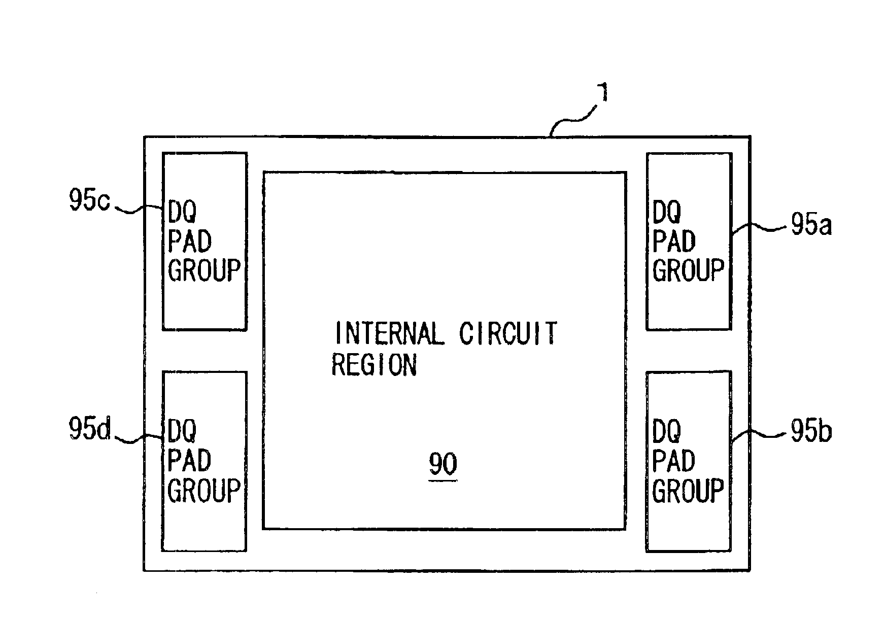
[0037]By arranging the data pads distributedly in the outer peripheral portions of the four divided regions of the semiconductor chip, it is possible to easily arrange the data pads corresponding to the ball grid array of the multi chip package even if the semiconductor chip is assembled in a multi chip package, and to utilize the semiconductor chip the same in configuration for the single chip package and for the multi chip package.
[0038]By separating the 1-bit test write data transfer bus line from the data line for transferring a multi-bit test read result in a multi-bit test, it is possible to distribute the circuits connected to the bus for writing and reading the test data, to mitigate bus load, and to transfer the data at high speed in a normal operation mode (since it is unnecessary to connect write / read data buses dedicated to the respective word structures to the same data bus line).
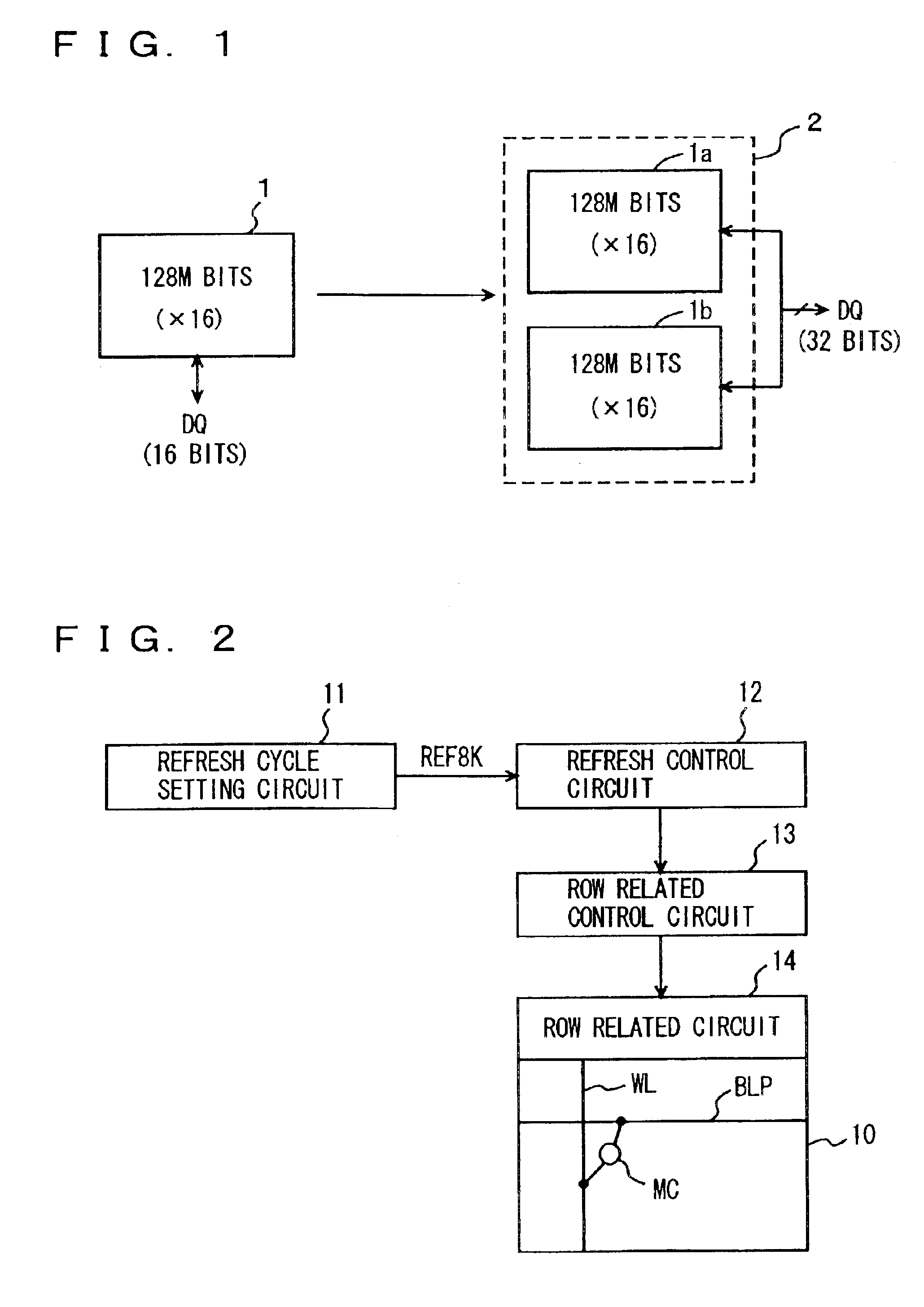
[0039]By changing the refresh cycle according to the type of the assembling package, it is possible to execute a refreshing operation in an optimum cycle in accordance with the storage capacity of the memory assembled in the package, ensuring retention of the storage data.
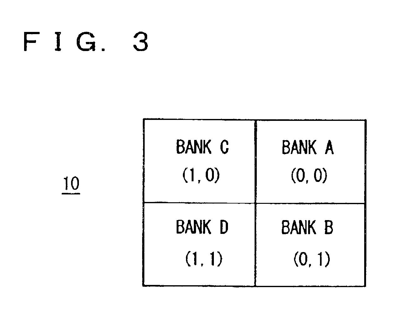
[0040]By applying data input / output mask signals to the memory circuits arranged corresponding to the respective four divided regions of the chip, it is possible to individually mask the data input / output in the respective four divided regions, to facilitate the connection between the data input / output mask pads and the data terminals, and to simplify the layout of wiring of data lines between the pads and terminals when the semiconductor memory chip is assembled in a multi chip package.
[0041]By setting the connection between the internal data bus lines and the pads at least in accordance with word structure information, it is possible to make the configuration of the internal read circuit such as a preamplifier common irrespectively of the word structure, simplifying the layout of the internal data read section.

Problems solved by technology

Therefore, semiconductor memory chips having a pad arrangement optimized for such a TSOP package cannot be applied to BGP.
In this case, if the required storage capacity is to be satisfied using two TSOPs, the area of memory chips disadvantageously increases to obstruct down-sizing of the portable equipment.
However, since MCP is of BGP, the memory chips suited for TSOP cannot be applied to MCP.

Method used


Image

  • Semiconductor circuit device adaptable to plurality of types of packages
  • Semiconductor circuit device adaptable to plurality of types of packages
  • Semiconductor circuit device adaptable to plurality of types of packages

Examples


ninth embodiment

[0104]FIG. 62 shows an example of the configuration of a data input / output section of the semiconductor circuit device in the ninth embodiment according to the present invention;

tenth embodiment

[0105]FIG. 63 is a schematic diagram showing the configuration of a main portion of a semiconductor circuit device in the tenth embodiment according to the present invention;

[0106]FIG. 64 concretely represents the relationship between an internal data bus and transfer data with the configuration shown in FIG. 63;

[0107]FIG. 65 is a schematic diagram showing the configuration of the important parts of a semiconductor circuit device in a modification of the tenth embodiment according to the present invention;

[0108]FIG. 66 concretely shows the relationship between an internal data bus line and multi-bit test transfer data with the configuration shown in FIG. 65;

[0109]FIG. 67 specifically represents the correspondence between the internal data line and the transfer data during a multi-bit test in the tenth embodiment according to the present invention;

eleventh embodiment

[0110]FIG. 68 is a schematic diagram showing the configuration of a main portion of a semiconductor circuit device in the eleventh embodiment according to the present invention;

[0111]FIG. 69 is a schematic diagram representing the correspondence between test data and data written to a memory cell in the eleventh embodiment according to the present invention;

[0112]FIG. 70 is a schematic diagram representing the correspondence between test data and data written to a memory cell in the eleventh embodiment according to the present invention;

[0113]FIG. 71 is a schematic diagram showing the correspondence between write data and external data in a normal operation mode in the eleventh embodiment according to the present invention;

[0114]FIG. 72 is a schematic diagram showing the configuration of a conventional single chip package;

[0115]FIG. 73 is a schematic diagram showing the arrangement of chips assembled in a conventional multi chip package; and

[0116]FIG. 74 is a schematic diagram showi...


PUM


Abstract

Data pad regions are arranged in four divided regions of a semiconductor memory chip of a rectangular shape, respectively, and data pads are selectively utilized in each of the four divided regions in accordance with a word structure. Thus, it is possible to implement a semiconductor memory chip capable of being assembled in both a single chip package and a multi chip package.

Description

BACKGROUND OF THE INVENTION[0002]1. Field of the Invention[0003]The present invention relates to a semiconductor circuit device, and particularly to a semiconductor circuit device assembled into a plurality of types of packages. More particularly, the present invention relates to the configuration of a semiconductor memory device with a common chip configuration allowing assembly into a plurality of types of packages.[0004]2. Description of the Background Art[0005]A semiconductor circuit formed on a semiconductor chip is assembled into a package before shipment as a final product. The semiconductor circuit is electrically connected to on-board wires through a pin terminal of the package, or the package protects the semiconductor chip against external contamination sources and external destructive factors such as external mechanical stress and external electromagnetism.[0006]Various types of packages are prepared according to the configuration of applicable board systems. Recently, a...

Claims


Application Information

Patent Timeline
Patent Type & Authority Patents(United States)
IPC IPC(8): G11C11/401G11C5/02G11C5/06G11C8/00H01L21/70G11C11/409G11C11/34G11C11/406H01L23/50G11C11/407H01L21/822H01L23/48H01L27/10H02J1/00H01L27/04G11C5/00
CPCG11C5/025G11C7/1045G11C8/10G11C11/406G11C11/40618G11C11/4093H01L2924/13091G11C2207/105G11C2211/4061H01L2224/32145H01L2924/01019H01L2924/01037H01L2924/01068H01L2924/01087H01L2924/00G11C7/00
Inventor SUWA, MAKOTOMATSUMOTO, JUNKOYAMAUCHI, TADAAKIOKAMOTO, TAKEOICHIGUCHI, TETSUICHIROYONETANI, HIDEKINAGASAWA, TSUTOMUTIAN, ZENGCHENG
Owner RENESAS ELECTRONICS CORP
Learn More