Inductive writer with flat top pole and pedestal defined zero throat

a write head and inductive technology, applied in the direction of metal sheet core heads, instruments, record information storage, etc., can solve the problems of difficult precise control of deposition process, difficulty in particular, and the inability to adequately focus duv or euv light within a very shallow depth range, so as to improve the magnetic properties of deposited materials and reduce the shadowing effect during dry etching processes , the effect of easy control of critical dimensions

Inactive Publication Date: 2005-03-22
WESTERN DIGITAL TECH INC
View PDF10 Cites 171 Cited by
  • Summary
  • Abstract
  • Description
  • Claims
  • Application Information

AI Technical Summary

Benefits of technology

An advantage of the present invention is that critical dimensions are more easily controlled during the fabrication process with a flat top pole.
is that critical dimensions are more easily controlled during the fabrication process with a flat top pole.
Another advantage of the present invention is that magnetic properties of deposited material is improved with a flat top pole.
And another advantage of the present invention is that shadowing effects during dry etch processes are reduced.
A further advantage of the present invention is that there is generally less damage due to over-milling which may occur when attempting to eliminate shadowing effects.
A yet further advantage is that much smaller track widths are achievable with a write head produced by using the present invention.

Problems solved by technology

The precise control of deposition processes is more difficult when dealing with contoured surfaces.
Difficulties are especially encountered when using advanced photolithography techniques involving very short wavelengths of light.
DUV or EUV light can only be adequately focused within a very shallow range of depth.
In addition, uniform thickness of photoresist material is difficult to achieve when there are variations in contour.
Magnetic properties of deposited materials are also less uniform when processed onto a contoured surface.
This can lead to unacceptable defects and poor manufacturing yields.
The fabrication of the top pole is, in fact, becoming a limiting factor in the quest for narrower track width.
This requires a very narrow and tall structure, with all the associated problems discussed above, when a top pole with a contoured top surface is used.

Method used


Image

  • Inductive writer with flat top pole and pedestal defined zero throat
  • Inductive writer with flat top pole and pedestal defined zero throat
  • Inductive writer with flat top pole and pedestal defined zero throat

Examples


case ii

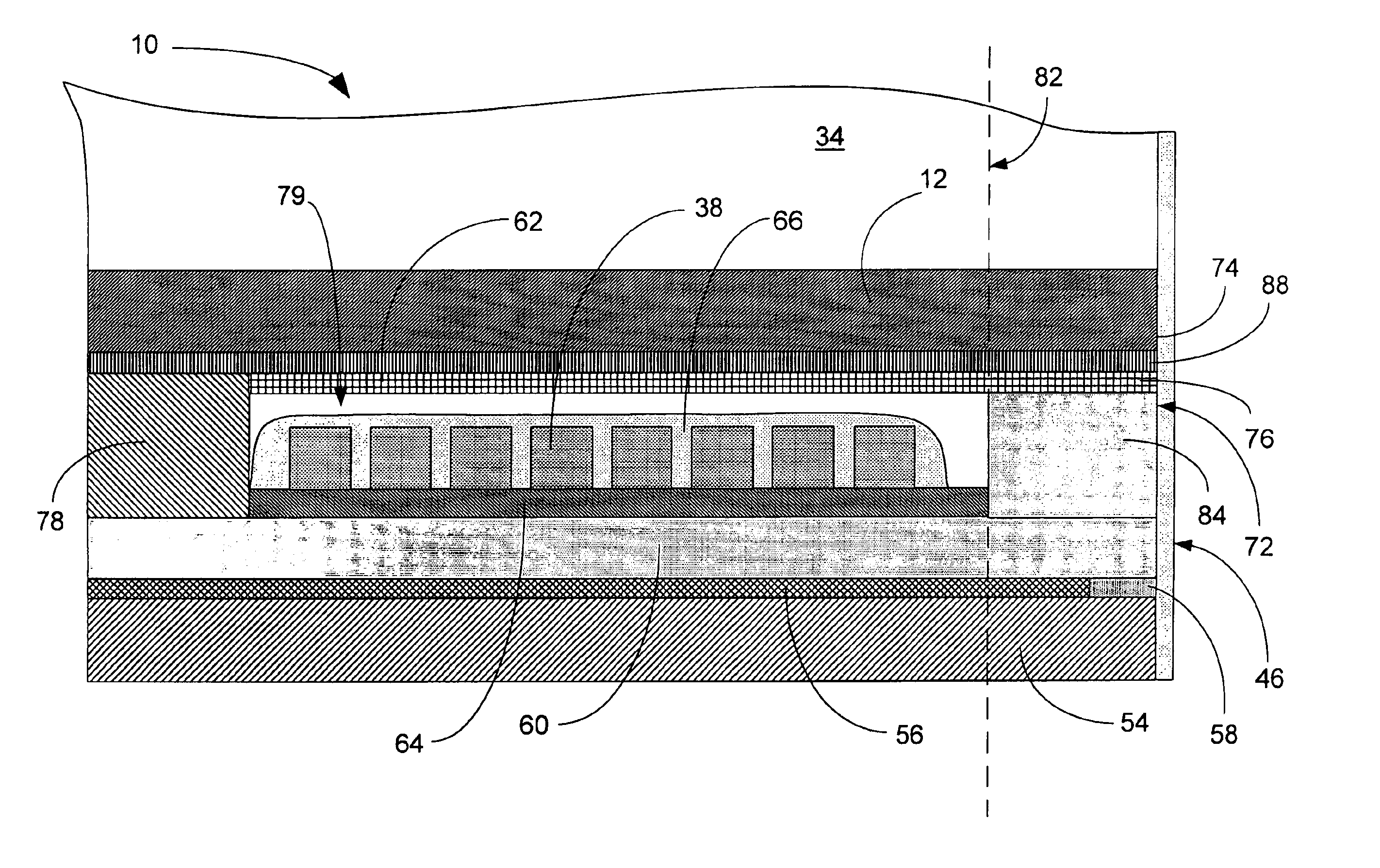
ss="uspto-list">A) Form the pedestal by either sputter deposition and patterning using ion milling or plating the pedestal into photo-resist mask 124;B) Deposit first insulation layer for coil 118;C) Use tri-level photo process to define coil structure followed by plating 120;D) Deposit second midcoat layer Al2O3 and Chemical Mechanical Polishing (CMP) 122.

In this process, the coils are inset below the pole tip topography onto an insulation layer (I1). In order to overcome the topography in the coil photo process the tri-level image transfer technique may be required. The following steps are needed for such process:a) Spin coat a planerizing photoresist, deposit a hard mask SiO2, spin coat and pattern an imaging photoresist layer;b) Use Reactive Ion Etching (RIE) to pattern the hard mask (e.g. using CHF3 or CHF4 containing etching process);c) Use RIE to pattern the bottom photoresist layer (e.g. using O2 plasma);c) Electroplating Cu coil;d) Hard mask and photoresist removal; ande) E...


PUM

PropertyMeasurementUnit
sizeaaaaaaaaaa
heightaaaaaaaaaa
lengthaaaaaaaaaa

Abstract

A disk drive write head (10) having a bottom pole (60), a first insulation layer (64) formed on the bottom pole (60), a coil (38) formed on the first insulation layer (64), a second insulation layer (66) formed on the coil (38), a write gap layer (76) formed on the second insulation layer (66), and a top pole (12) formed on the write gap layer (76), where the top pole (12) is substantially flat.A second embodiment (100) is described which is produced by a damascene process.

Description

TECHNICAL FIELDThe present invention relates generally to inductive write heads used in magnetic media storage devices, and more particularly to magneto-resistive disk drive heads.BACKGROUND ARTA computer disk drive stores and retrieves data by positioning a magnetic read / write head over a rotating magnetic data storage disk. The head, or heads, which are typically arranged in stacks, read from or write data to concentric data tracks defined on surface of the disks which are also typically arranged in stacks. The heads are included in structures called “sliders” into which the read / write sensors are imbedded during fabrication. The goal in recent years is to increase the amount of data that can be stored on each hard disk. If data tracks can be made narrower, more tracks will fit on a disk surface, and more data can be stored on a given disk. The width of the tracks depends on the width of the read / write head used, and in recent years, track widths have decreased as the size of read...

Claims


Application Information

Patent Timeline
Patent Type & Authority Patents(United States)
IPC IPC(8): G11B5/39G11B5/31G11B5/012G11B5/33
CPCG11B5/3116G11B5/3146G11B5/3967G11B5/313G11B5/012Y10T29/49044
Inventor CHEN, YINGJIANWANG, JAMESHE, QINGDONG, ZI-WENSEAGLE, DAVID J.
Owner WESTERN DIGITAL TECH INC
Why Eureka
Try Eureka