Filters implemented in integrated circuits
a filter and integrated circuit technology, applied in the field of communication, can solve the problems of limited circuit designers' ability to use these components in the fully integrated, the inability to fabricate high-q capacitors and inductors in high-density radio frequency integrated circuit (rf ic) technologies based on silicon, and the inability to achieve bipolar process improvements that are not feasible, and achieve high-q filtering
- Summary
- Abstract
- Description
- Claims
- Application Information
AI Technical Summary
Benefits of technology
Problems solved by technology
Method used
Image
Examples
Embodiment Construction
This invention introduces a high-Q narrow-band, passive (notch) filter for use at frequencies exceeding 800 MHz, fabricated with metal-insulator-metal (MIM) capacitors and an on-chip inductor with a Q factor of approximately 3-10, implemented on a conductive silicon substrate. Typically, a single filter module implemented according to this invention provides approximately 50 dB of rejection at 2.4 GHz with a 2% bandwidth.
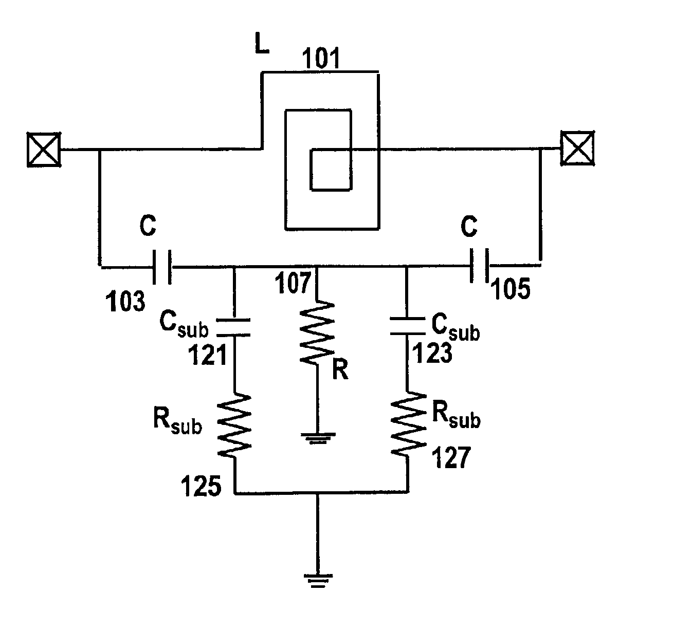
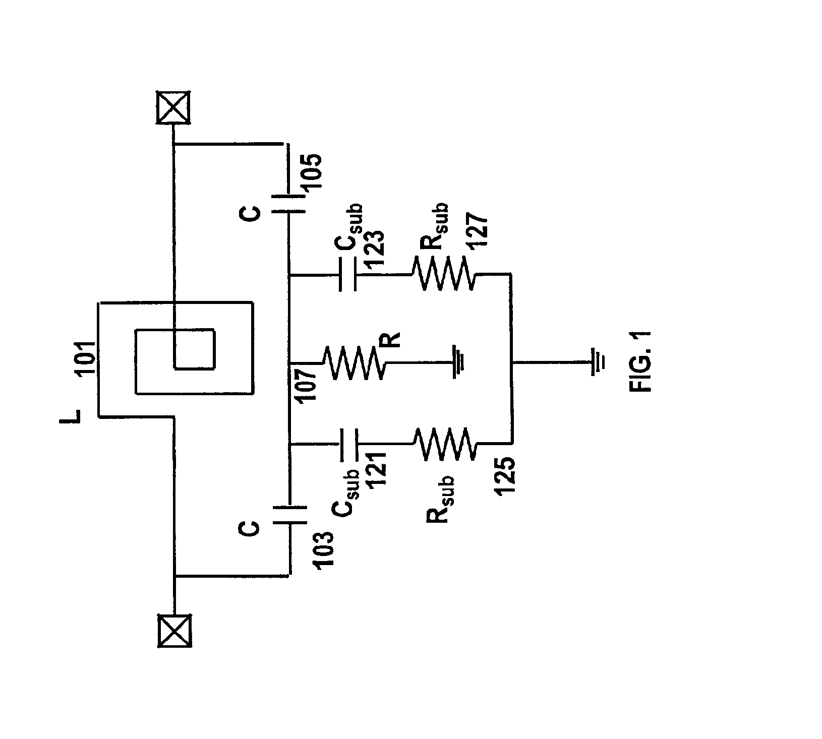
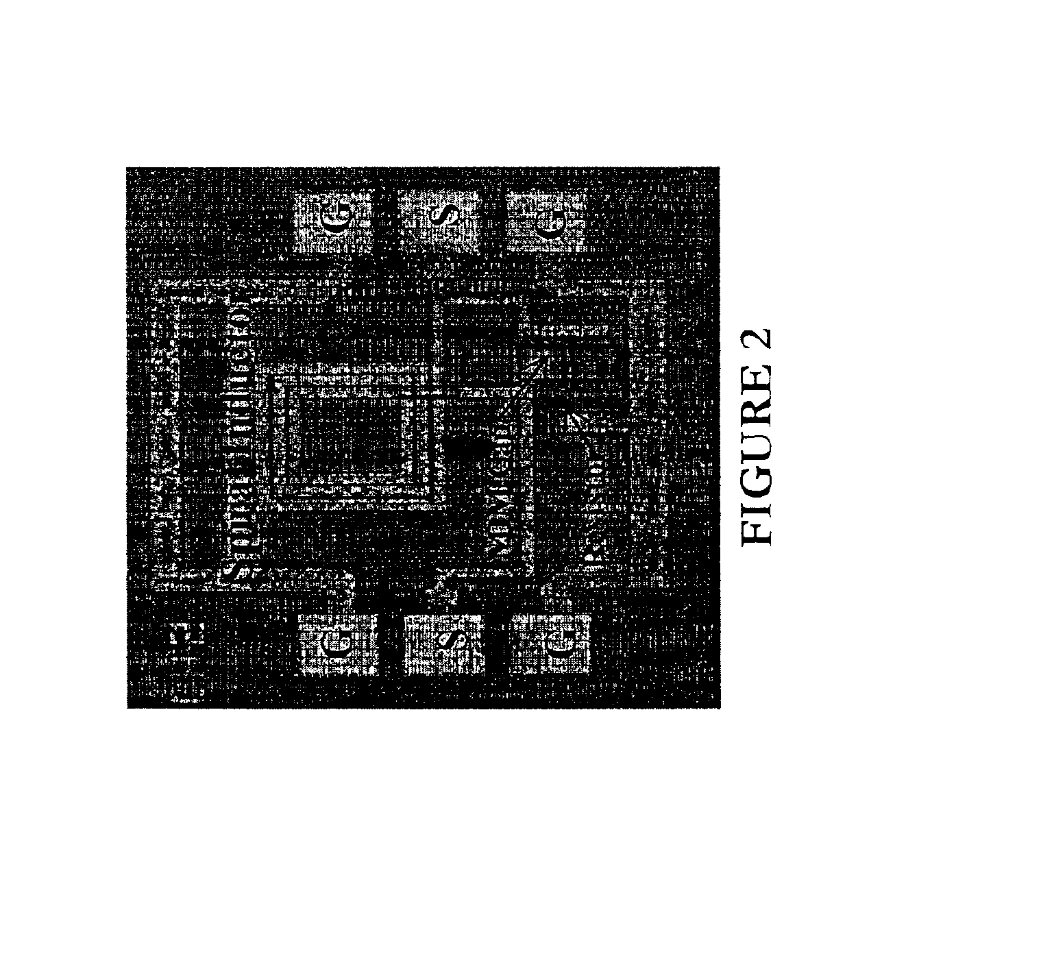
Referring first to FIG. 1, the invention consists of an on-chip inductor L 101, capacitors C 103, 105, and resistor R 107. The inductor 101 and the capacitors 103, 105 can have low Q values (e.g. ˜3). Also shown are the various parasitic components that are associated with the layout of the MIM capacitors 103, 105. These parasitic components, Csub 121, 123 and Rsub 125, 127, affect the actual notch frequency of the circuit as explained later. All of these components are implemented as integrated components in a silicon-based RF integrated circuit technology. FIG. 2 ...
PUM
 Abstract
Description
Claims
Application Information
 - R&D
- Intellectual Property
- Life Sciences
- Materials
- Tech Scout
- Unparalleled Data Quality
- Higher Quality Content
- 60% Fewer Hallucinations
Browse by: Latest US Patents, China's latest patents, Technical Efficacy Thesaurus, Application Domain, Technology Topic, Popular Technical Reports.
© 2025 PatSnap. All rights reserved.Legal|Privacy policy|Modern Slavery Act Transparency Statement|Sitemap|About US| Contact US: help@patsnap.com


