
Device for plasma incision of matter with a specifically tuned radiofrequency electromagnetic field generator

a radiofrequency electromagnetic field and generator technology, applied in plasma welding apparatus, manufacturing tools, surgery, etc., can solve the problems of inefficiency of one hardened matter attempting to cut through another hardened matter, substantial bums or volatilization of matter, and significant inefficiencies, so as to reduce the chaos of atomic particles, and high efficiency

Inactive Publication Date: 2005-03-15
RJF HLDG II
View PDF19 Cites 8 Cited by
  • Summary
  • Abstract
  • Description
  • Claims
  • Application Information

AI Technical Summary

Benefits of technology

"The invention is a device that generates and amplifies electromagnetic waves for use in surgical procedures. The device is designed to interact with atoms and molecules at the surface of the surgical instrument, using a process called plasma formation. This interaction results in the transformation of atoms to higher energy levels, which then move quickly through space and collide with other atoms, creating a chain reaction that triggers the formation of a cloud of plasma. The device is designed to match the impedance, frequency, and power of the plasma cloud, resulting in a harmonious and controlled plasma that focuses energy into the intended path of incision, leading to a more efficient and controlled surgical incision."

Problems solved by technology

Such purely physical methods of one hardened matter attempting to cut through another hardened matter are inefficient and therefore experience significant inefficiencies such as frictional resistance when the matter being incised is solid and dense such as biologic tissue, wood products or even metal.
When these types of devices are used to place an incision into matter, uncontrolled plasma arcs induce substantial bums or volatilization of matter while electrical ohmic resistance in the matter to be incised creates a heating effect due to phenomenon such as dielectric hysteresis and eddy currents.
This approach has received limited use since its shortcomings include extensive damage to matter outside of the intended incision path with the resultant production of burning and charring which frequently causes unpleasant smelling fumes.
The inefficiency of classic electro-incision units is manifested by the high power needed to produce a cutting effect at the incising tip, usually in excess of 50 watts of power.
This relatively high power output needed in classic electro-cutting or electrosurgical units is secondary to the cutting inefficiency of these units which operate on a combination of classic ohmic diathermy as well as unstable, uncontrolled, caustic plasma arcing which is a form of disharmonious plasma.
Lasers have also been used to incise and cut; however, these units are expensive and require a large amount of system input energy to create a laser beam with sufficient power to cut or make an incision into matter.
The atomic particle turbulence in plasma arcs represents a form of atomic particle chaos and the uncontrolled nature of the atomic particle chaos causes a substantial quantity of energy spillover into matter outside of the intended path of incision and thereby may produce excessive heating.
This level of substantial heating is produced when unwanted arcing occurs with classic electrocutting or electrosurgical units.
This energy spillover into matter surrounding the intended path of incision into matter results in energy exposure and damage to the surrounding matter.
(a) to provide an incisional device that uses an inexpensive electronic radiofrequency signal generator, amplifier, impedance matching and output conditioning network, as well as a transmitter probe to generate, amplify, condition and transmit an electromagnetic wave.
(b) to employ a solid, non-hollow conductive radiofrequency transmitter probe to create, maintain and control plasma. Nonetheless, the transmitter probe may be completely hollow or partially hollow in design.
(c) to produce a plasma cutting blade from an electronic electromagnetic field generator system which requires lower system input energy relative to other electrocutting incisional methods presently in use, even as low as 2 watts of average input power. Likewise, this system requires lower system output energy relative to other electrocutting incisional methods presently in use, even as low as 1 watt of average output power.
(d) to create a cutting plasma cloud without the necessity of injecting an ionizable gas into the field of cutting as is seen in plasma generating devices such as plasma torches and etching systems in plasma chambers.
(e) to create a harmonious plasma cloud with substantially reduced atomic particle chaos and turbulence than other plasma cutting devices by impedance matching and conditioning the energy from our electromagnetic generator system to the plasma cloud that surrounds and coats the activated transmitter incising electrode tip.
(f) to create a harmonious plasma cloud with substantially reduced atomic particle chaos and turbulence than other plasma cutting devices by frequency matching the energy from our electromagnetic generator system to the atomic particle oscillation harmonics and precession frequencies of the plasma cloud which coats and surrounds the activated transmitter incising electrode tip.
Furthermore, this electromagnetic radiation reflected back into the plasma cloud acts to further energize the harmonious plasma cloud thereby further reducing the output energy required from the electromagnetic generator system to sustain the plasma cloud for effective cutting.

Method used


Image

  • Device for plasma incision of matter with a specifically tuned radiofrequency electromagnetic field generator
  • Device for plasma incision of matter with a specifically tuned radiofrequency electromagnetic field generator
  • Device for plasma incision of matter with a specifically tuned radiofrequency electromagnetic field generator

Examples


Embodiment Construction

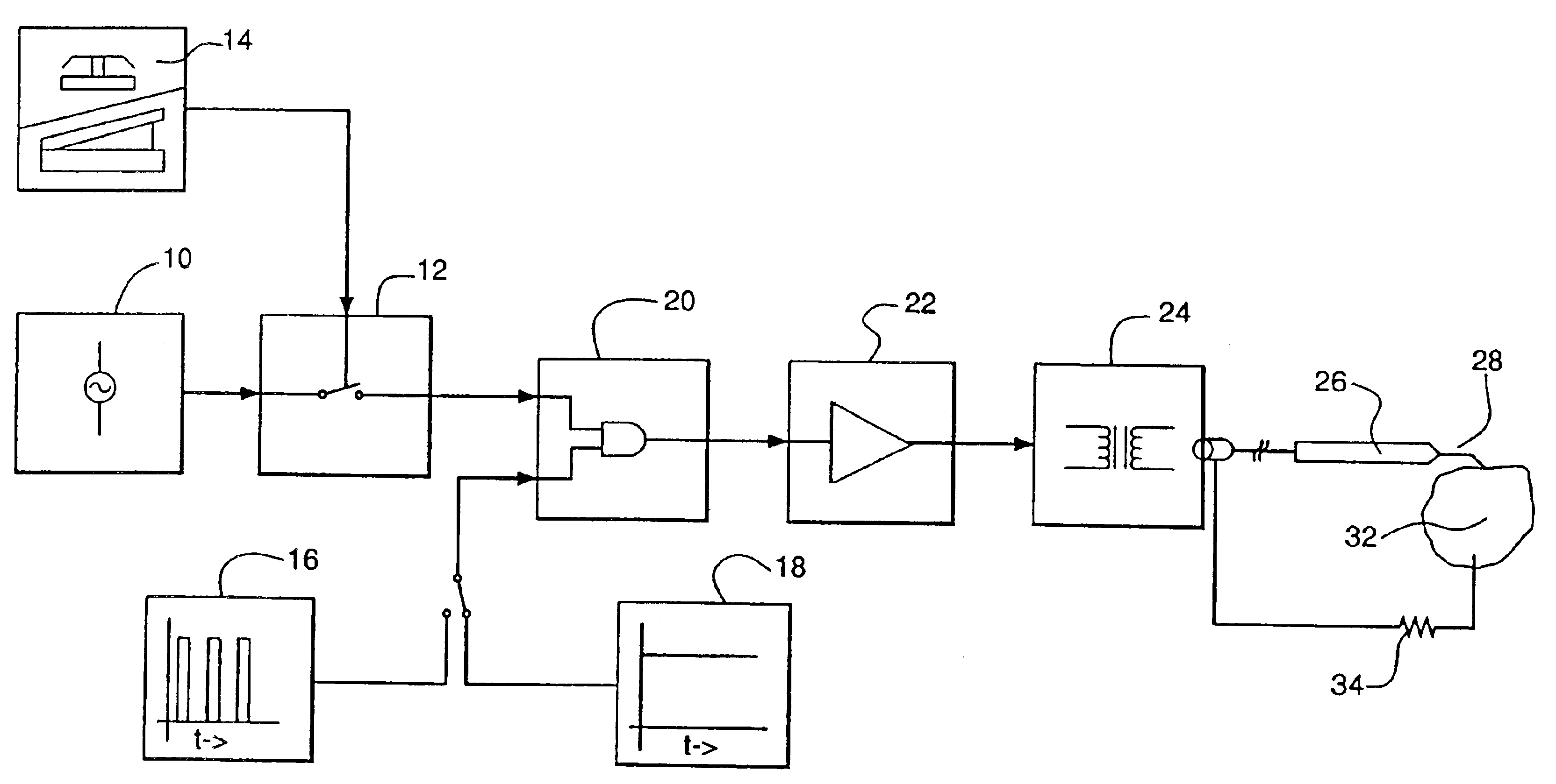
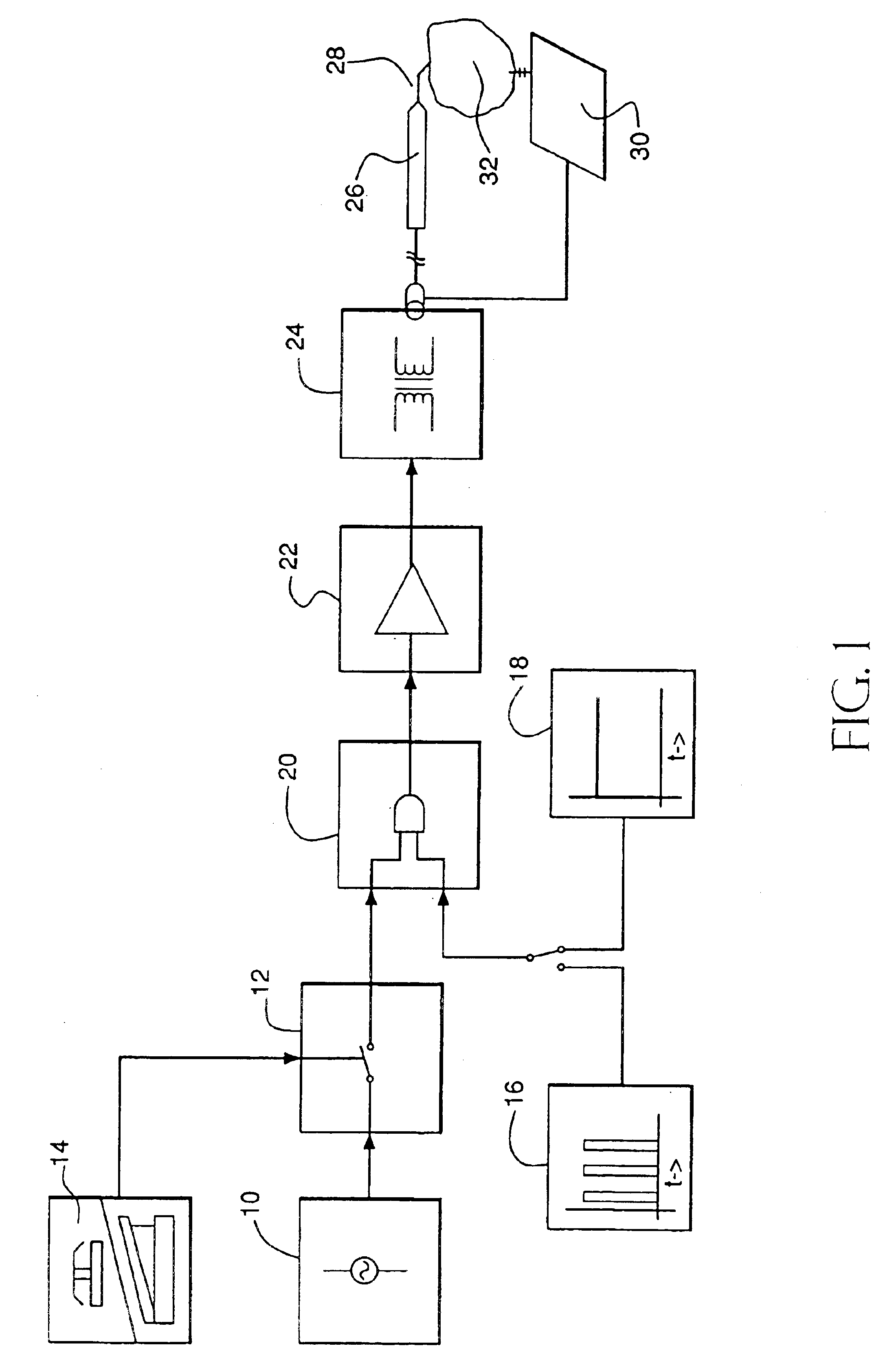
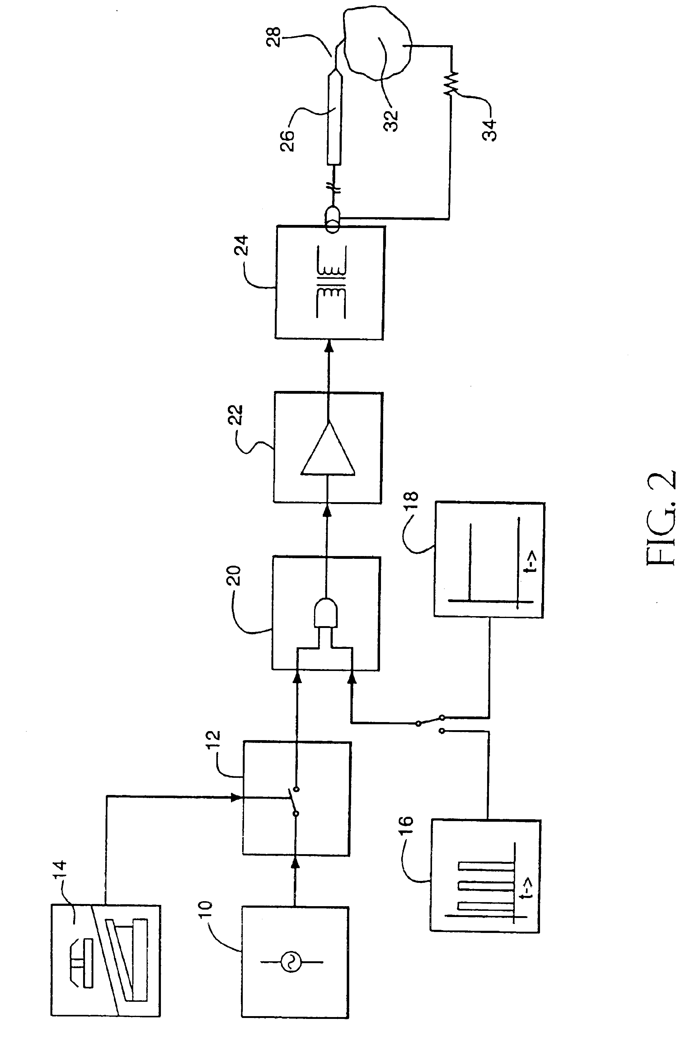
A typical embodiment of the plasma incision device of the present invention is illustrated in FIG. 1 and FIG. 2. An output signal of a radiofrequency signal generator (10) is switched on and off with a radiofrequency switch (12) by several means such as an on-off button or on-off switch (14). The output signal of the radiofrequency signal generator is then slaved through a single gate (20) to either burst mode duty cycle generator (16) or a continuous mode free running generator (18). The burst mode or continuous mode radiofrequency output signal is then amplified through a power amplifier (22). The output signal of the power amplifier is then conditioned with an impedance matching and output conditioning network (24) and is then channeled into an active incising transmitter handpiece (26). When activated, an incising electrode tip (28) at the extreme end of incising transmitter handpiece (26) is coated with a plasma cloud which is used to place an incision path into the matter into...


PUM

PropertyMeasurementUnit
poweraaaaaaaaaa
poweraaaaaaaaaa
average poweraaaaaaaaaa

Abstract

A device to place an incision into matter with a harmonious plasma cloud. A radiofrequency generator system produces pulsed or continuous electromagnetic waveform which is transmitted by an active transmitter incising electrode tip. This generated electromagnetic wave is utilized to initiate a plasma cloud with processes such as thermal ionization and a photoelectric effect which then trigger an Avalanche Effect for charged atomic particles at the surface of the active transmitter incising electrode tip. This electromagnetic wave is impedance matched, frequency matched, power matched and tuned to the plasma cloud in order to sustain and control a harmonious plasma cloud with reduced atomic particle turbulence and chaos. This harmonious plasma cloud forms a coating over the surface of the active transmitter electrode tip as well as acts to reduce the energy needed from the power amplifier of our plasma cutting device. The electromagnetic wave is also used to produce a Pinch Effect to compress, contour, shape and control the harmonious plasma cloud. The electromagnetic wave is furthermore used to trap and contain the plasma cloud without the need of a solid matter containment vessel according to the Magnetic Bottle Effect of physics and a generated centripetal electric field force that acts to pull plasma particles inward toward the activated incising electrode tip. The Tunnelling Effect of physical chemistry is utilized to focus and amplify the energy delivered to the harmonious plasma cloud while shielding matter surrounding the intended path of incision from potential electromagnetic radiation exposure. The invention is an efficient, effective, safe, clean and inexpensive device which can be used to place an incision in matter.

Description

BACKGROUND1. Field of InventionThis invention relates to a plasma generation device employed to place an incision into matter with a harmonious plasma cloud, specifically to harmonious plasma clouds initiated and sustained by electromagnetic energy waves transmitted from a radiofrequency signal generator system. This system is impedance matched, frequency matched and output power matched to the incising harmonious plasma cloud which is initiated, sustained and controlled by our device and in the process coats the activated transmitter incision probe of our invention.2. Description of Prior ArtHardened physical blades, such as a metal blade, a sapphire blade, or a diamond blade are the devices most frequently employed to place an incision into matter. Such incisions are based on frictional physical interactions between a sharp, acute edge of hardened matter against a surface of the matter to be incised. Such purely physical methods of one hardened matter attempting to cut through ano...

Claims


Application Information

Patent Timeline
Patent Type & Authority Patents(United States)
IPC IPC(8): B23K10/00B23K9/00A61BA61B17/32A61B18/00A61B18/12A61B18/14A61B18/18H05H1/24H05H1/46
CPCA61B18/042A61B18/1402B23K10/006A61B18/1206A61B2018/00875A61B2018/1213A61B2018/00702H05H1/46H05H1/466H05H2245/32B23K10/00
Inventor FUGO, RICHARD J.COCCIO, DAMIAN
Owner RJF HLDG II
Learn More