
Static cache

a cache and static technology, applied in the field of processor technology, can solve the problems of disturbing the disadvantages of cache systems of the prior art, the use of multi-level cache systems has not been employed in embedded processors, and the same degree of real-time systems, so as to ensure the predictability of program performance, eliminate or reduce, and fine granularity

Inactive Publication Date: 2005-03-08
TELEFON AB LM ERICSSON (PUBL)
View PDF13 Cites 15 Cited by
  • Summary
  • Abstract
  • Description
  • Claims
  • Application Information

AI Technical Summary

Benefits of technology

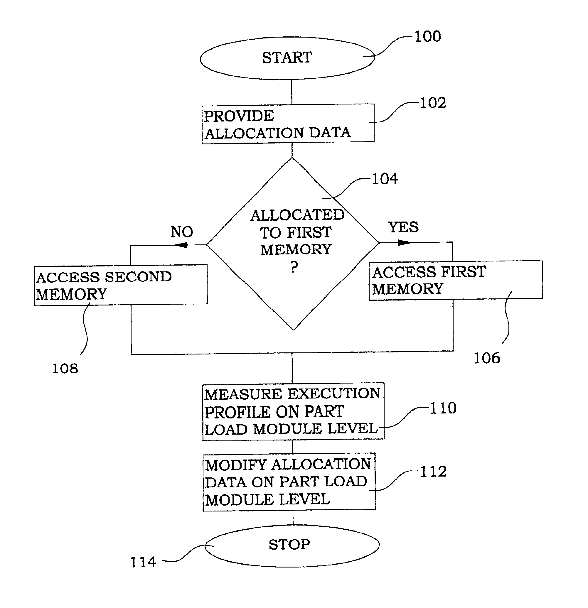
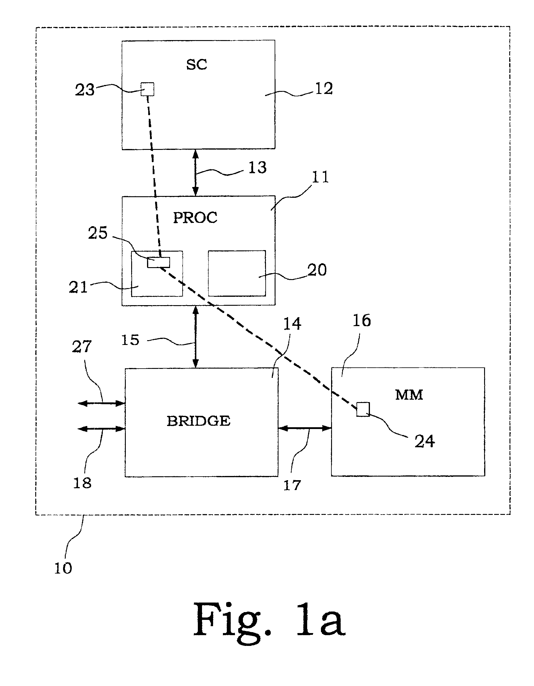
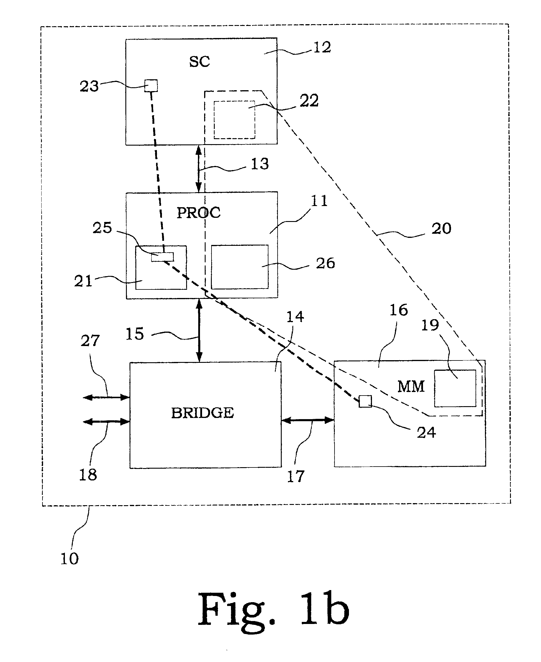
A general object of the present invention is to provide a memory configuration and memory handling of random access memories, which eliminate or reduce the above disadvantages. Another object of the present invention is to provide a memory configuration and memory handling, which ensure predictability in program performance. A further object of the present invention is to provide a processor system with possibilities for periodically statically allocating the most performance critical variable / record data and / or instruction data with a fine granularity to fast memory areas in an updateable manner. Yet a further object of the present invention is to use execution profiling as a base of memory allocation updating. Another object of the present invention is to provide a processor system with a static cache memory with low latency.
Thus, the present invention provides a memory area, which may be described as a “static cache”. One of the main advantages with the present invention is that a fine granularity of the data held by the static cache reduces the necessary memory sizes, or allows for more important data to be held in the static cache. Furthermore, the close arrangement to the processor lowers the access times. The possibility to intermittently update the allocation based on execution profile measurements gives an increased flexibility in the use of the present invention.

Problems solved by technology

However, the use of multi-level cache systems has not been employed for embedded processors (i.e. processors not “visible” for any specific user) and real-time systems to the same degree.
When working with embedded processors and / or real-time systems, some of the disadvantages with cache systems of the prior art become disturbing.
There is a lack of determinism, which is particularly troublesome in real-time applications.
There are also problems in system maintenance.
First, standard multi-level caches present an unpredictable and varying behaviour concerning performance and / or delays.
Furthermore, in contrary to real-time processors, general-purpose processors do not have any absolute deadline in processing time to meet.
Furthermore, interactions between the cache system and the maintenance of the system, such as background tests or updates in a fault tolerant computer, may considerably change the performance of the cache system.
For instance, the execution of a memory test program or the copying of a large memory area for a backup or hardware re-integration can invalidate all content in a cache that is used by the ordinary applications.
For large applications with continuous development and several hardware platforms with different memory configurations, it is in practice impossible to keep up and create optimal configurations for each application and hardware combination.
Furthermore, the introduction of run-time linking for supporting dynamic changes of software in a system, makes it even more difficult for an application developer to select appropriate data for storage in the fast and slow memory areas, respectively.
This works well for real-time applications with a single critical routine or a few critical routines, but does not allow for scaling to large applications.
However, the benefit of such a configuration is limited, since the division is based on a coarse granularity.
Program blocks have often sizes in the order of 100 kB and variable / record data blocks could even reach to MB-sizes, which reduces the efficiency of the memory division, since only a few blocks can be accommodated in the faster memory.
Processes of accessing main memories of a RAM type are not applicable.

Method used


Image

  • Static cache
  • Static cache
  • Static cache

Examples


Embodiment Construction

The term data will generally refer to all kind of data, such as variable / record data, instruction data, reference data or a combination thereof.

In the following description, the term “variable” or “variable / record data” is used for different types of data, including e.g. a number, a record, a vector or a matrix of numbers. This kind of “variable” is in many applications also referred to as a “record”. The terms will in the following description be treated as synonymous words.

Instruction data or program data may comprise instructions, procedures, functions, routines and classes associated with programs, and is referred to as “instruction data” in the following description.

A load module is a quantity of data, both instruction data and associated variable / record data, which is loaded in order to be able to execute a certain program. In a personal computer (PC), this corresponds to an “EXE”-file, in Java, it is named “class file” and in the APZ system it is a “block”. The data blocks of...


PUM


Abstract

The present invention discloses a processor system comprising a processor (31) and at least a first memory (32) and a second memory (34, 36, 37). The first memory (32) is normally faster than the second one, and means for memory allocation (38, 41, 48) perform the periodically static allocation of data into the first memory (32). The means for memory allocation (38, 41, 48) are run-time updateable by software. An execution profiling section (39) is provided for continuously or intermittently providing execution data used for updating the means for memory allocation (38, 41, 48). According to the invention, the memory allocation is performed on a variable or record (49, 50) level. The means for memory allocation preferably use linking tables (41, 48) supporting dynamic software changes. The first memory (32) is preferably an SRAM, connected to the processor by a dedicated bus (33).

Description

This application claims priority under 35 U.S.C. §§ 119 and / or 365 to 0000533-0 filed in Sweden on Feb. 18, 2000; the entire content of which is hereby incorporated by reference.TECHNICAL FIELDThe present invention relates to processor technology in general and in particular to memory functionality of a processor.BACKGROUNDEver since the first computers, programmers have wanted unlimited amounts of fast memory. The processing times have decreased considerably during recent years, but the access times to different kinds of memories have not developed with the same rate. Already from the beginning of computer science, one has been aware of that certain large advantages can be achieved by organising the memory system in a hierarchy. The use of caches is one of the major performance enhancements of modern microprocessors. The term “cache” is here intended to be used for “the level of the memory hierarchy between the central processing unit and the main memory”. One important feature of ...

Claims


Application Information

Patent Timeline
Patent Type & Authority Patents(United States)
IPC IPC(8): G06F12/08G06F11/34G06F12/0802
CPCG06F9/5016G06F12/0802G06F11/3409G06F2201/88G06F2201/885
Inventor HOLMBERG, PER ANDERSNORRMAN, PETERJOHANSSON, LEIF KARLEGELAND, TERJE
Owner TELEFON AB LM ERICSSON (PUBL)
Learn More