Smart-ultrasonic/sonic driller/corer

Inactive Publication Date: 2005-03-08
GYRUS ACMI INC (D B A OLYMPUS SURGICAL TECH AMERICA)
View PDF6 Cites 57 Cited by
  • Summary
  • Abstract
  • Description
  • Claims
  • Application Information

AI Technical Summary

Benefits of technology

[0006]Existing drilling techniques are limited by the need for high axial forces, large power consumption, as well as a need to operate from an heavy platform to drill in non-horizontal and / or hard surfaces. The life of coring bits is markedly reduced by the breakdown of the binder that holds abrasive material on a bit surface.
[0011]The present invention provides apparatus that can probe a medium for selection of drilling direction and operation parameters for optimal operation, extract samples of various forms and provide a platform for sensors to perform real time in-situ or remote post analysis. Outboard sensors provided information related to probing activity of the apparatus as well as sample analysis during penetration of a medium. Apparatus in accordance with the present invention is light weight and consumes low amounts of power / energy, in addition, operate at low and high temperatures at a plurality of pressure levels.SUMMARY OF THE INVENTION
[0012]Apparatus for probing, testing and penetrating a medium in accordance with the present invention, generally includes an actuator for generating vibrations at ultrasonic frequencies and a horn coupled to the actuator for amplifying the actuator vibrations. The horn may be solid or include a central bore therethrough. A non-rotating drilling bit is provided for penetrating the medium with the bit having a drill stem communicating with the horn. A bore through the bit may be provided and in communicating with the horn bore when provided. The apparatus in accordance with the present invention utilizes a low axial load, which minimizes drill walk and requires a very small torque force and consumes very little power due to the non-rotating configuration of the bit.
[0015]In one embodiment of the present invention, the ultrasonic actuator may include a piezoelectric stack, for example, a metal-piezoceramic-metal sandwich which enables operating over a very wide temperature range.

Problems solved by technology

Existing drilling techniques are limited by the need for high axial forces, large power consumption, as well as a need to operate from an heavy platform to drill in non-horizontal and / or hard surfaces.
Accordingly, the capability of existing rotary corers has limited application in power and mass constrained environments.
Such drilling rigs cannot be duty cycled without a staggering loss of efficiency.
In addition, because the grinding mechanism is determined by the compression failure of the rock, the sharp teeth of the corers must be re-sharpened frequently.
This increase is accompanied by a concomitant drop in drilling efficiency and often causes burning or melting of the drill bit.
Unfortunately, for modern technologies, the ratio of down-the-well power delivered verses input power generation is below several percent verses 10 to 30 percent for conventional drills.
Accordingly, many space or power limited applications simply do not have enough power to employ a non-traditional drilling technique.

Method used


Image

  • Smart-ultrasonic/sonic driller/corer
  • Smart-ultrasonic/sonic driller/corer
  • Smart-ultrasonic/sonic driller/corer

Examples


Embodiment Construction

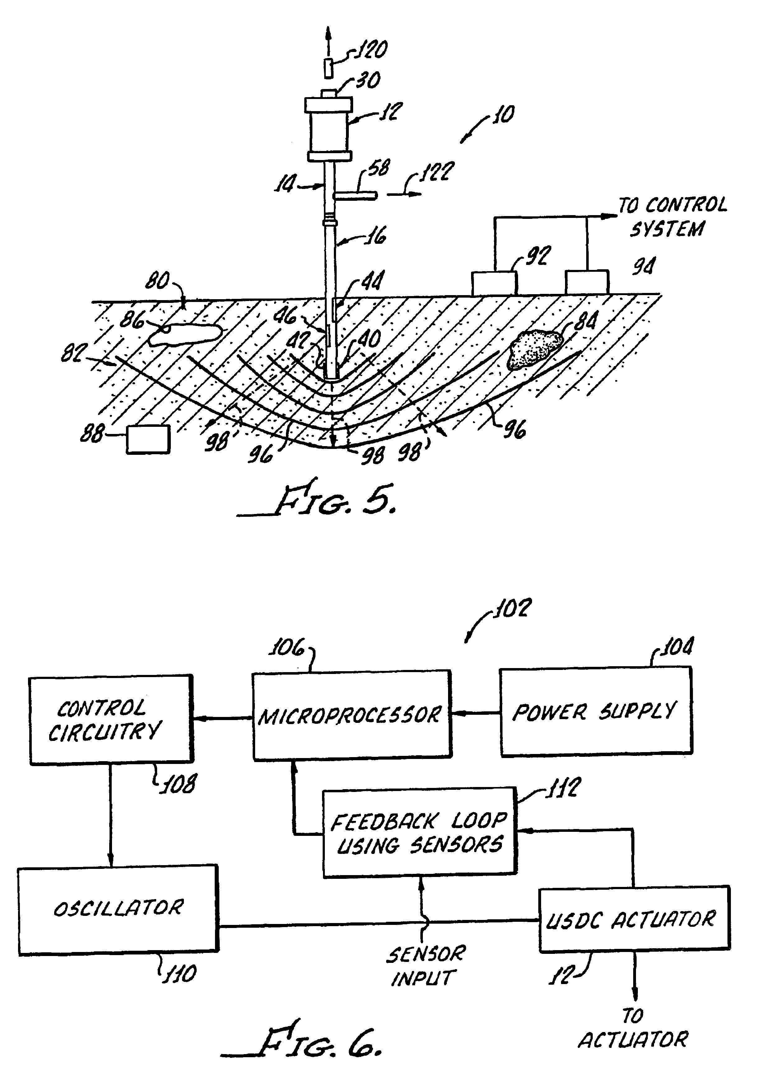
[0027]With reference to FIGS. 1-3, there is shown, in partial cross-section, apparatus 10 for probing, testing and penetrating a medium (not shown in FIG. 1) which generally includes an actuator 12 having a horn 14 coupled thereto for amplifying the actuator vibrations;

[0028]A non-rotating coring and drilling bit 16 includes a bit tip 18 and a drill stem 20, the latter communicating with the horn 14 as will be hereinafter described. The bit 16 and horn 14 may be solid, however as illustrated, a bore through the bit 16 communicates with a bore 26 through the horn 14 and a bore 28 through a bolt 30 for enabling sampling as hereinafter in greater detail.

[0029]The bit 16 may be formed from various high stiffness materials, metal alloys or polymers having a length of up to 5 feet and a diameter of between about 0.008 inches and about 30 inches. Because the bit 16 is non-rotating, any shaped cross-section of the bit may be utilized.

[0030]The actuator 12 and horn 14 may be coupled to one a...


PUM


Abstract

Apparatus for probing, sensing, testing penetrating and sampling a medium generally includes an actuator (12) for generating vibrations at ultrasonic frequencies and a horn (14) coupled to the actuator (12) for amplifying the actuator vibrations along with a non-rotating coring and drilling bit (16) for penetrating the medium. A bit (16) includes a drill stem (20) attached to the horn (14) and a bore (26) extends through the bit (16), horn (14) and actuator (12) for withdrawal of samples. A free mass (36) is disposed between the horn (14) and the drill stem (20) for oscillating therebetween in response to the actuator vibration for causing migration of medium debris around and through the actuator bore for effectively self-cleaning of the bit (16). The hammering action of the free mass (36) is used for penetration of the medium and for analysis of the medium though the use of spaced apart accelerometers (92 and 94).

Description

[0002]This application claims benefit of Ser. No. 60 / 201,650 filed May 3, 2000.[0003]The present invention generally relates to the field of ultrasonic drilling, and more particularly, relates to apparatus for probing, testing, and penetrating a medium.[0004]Effective probing, drilling and coring apparatus finds use in a great number of areas such as, for example, planetary exploration, military, medical operations, construction, police investigations, geology, archaeology sports (for example hiking and rock climbing) and other games.[0005]To assure effective operation it is preferable to have probing capability for pre-screening at the medium. For different measurement techniques, various forms of samples are needed and real time sensing and analysis with minimum destruction of the surroundings is highly desirable. The need for such capability has risen sharply with the evolution of the NASA objective to collect samples, conduct planetary in-situ analysis and return such samples to...

Claims


Application Information

Patent Timeline
IPC IPC(8): E21B7/00E21B7/24E21B44/00E21B47/00E21B49/00
CPCE21B7/24E21B44/00B64G4/00E21B49/00E21B47/00
Inventor BAR-COHEN, YOSEPHSHERRIT, STEWARTDOLGIN, BENJAMINPETERSON, THOMAS M.PAL, DHARMENDRAKROH, JASONKRAHE, RON
Owner GYRUS ACMI INC (D B A OLYMPUS SURGICAL TECH AMERICA)
Why Eureka
Try Eureka