
Negative working photosensitive lithographic printing plate

a lithographic printing plate and negative technology, applied in the field of negative working photosensitive lithographic printing plate, can solve the problems of insufficient cure of exposed areas, inability to achieve high printing durability (i.e., high press life), and difficulty in further improvement of productivity, etc., to achieve high productivity, high printing durability, and low irradiation energy per unit area

Inactive Publication Date: 2005-03-01
FUJIFILM CORP
View PDF9 Cites 34 Cited by
  • Summary
  • Abstract
  • Description
  • Claims
  • Application Information

AI Technical Summary

Benefits of technology

Accordingly, an object of the present invention is to eliminate the above-described drawbacks of the conventional techniques and to provide a negative working photosensitive plate (including the printing plate precursor), especially one suitable for image-drawing with a laser light, from which a lithographic printing plate having sufficient printing durability (i.e., sufficient press life) can be obtained with high productivity even through exposure conducted under such conditions that the irradiation energy per unit area is low.
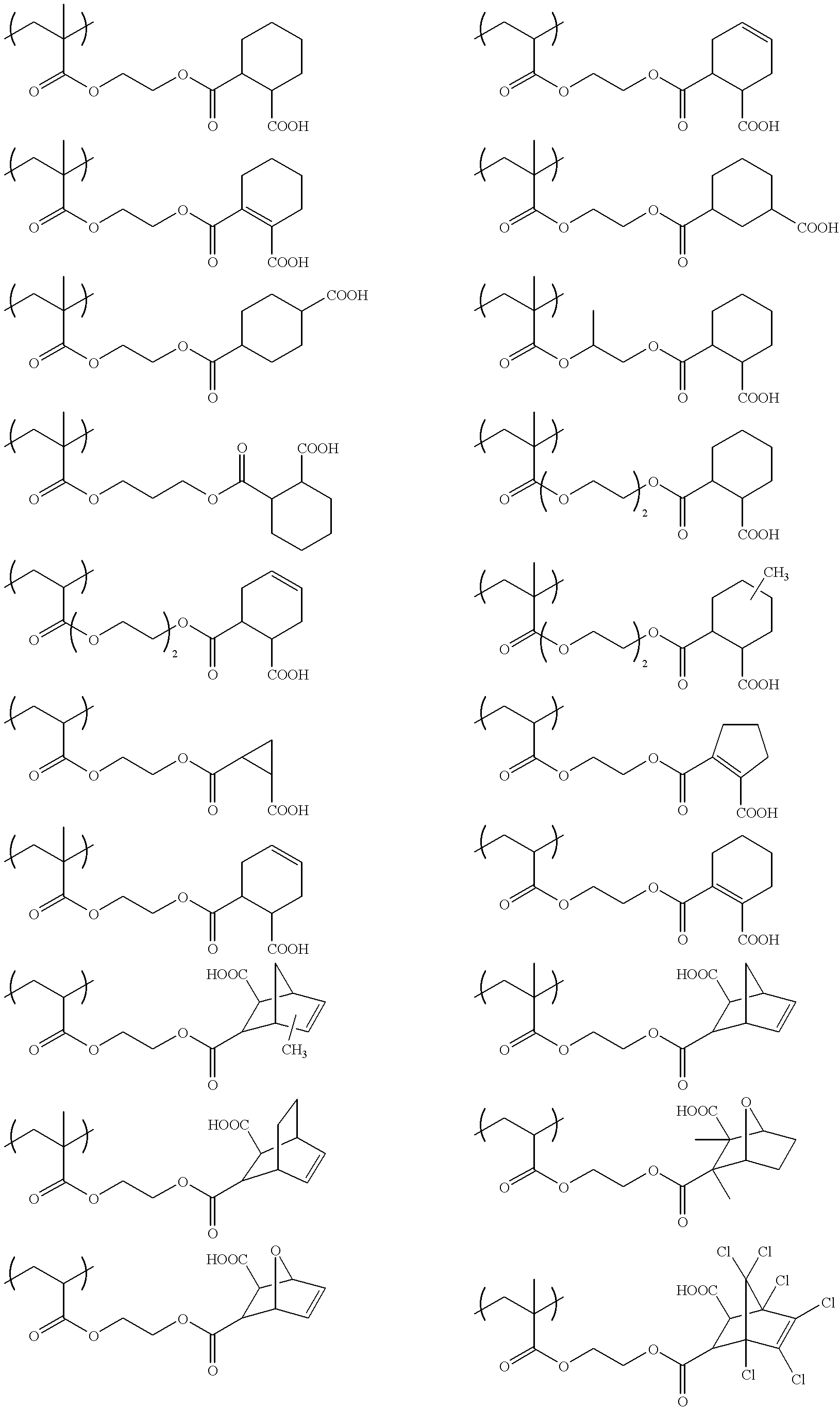
One of the features of the negative working photosensitive lithographic printing plate of the present invention is that a (meth)acrylic acid ester having both of one or more carboxyl groups and an alicyclic hydrocarbon structure was used as a comonomer for imparting alkali developability to the polymeric binder. Due to the use of the comonomer, the negative working photosensitive lithographic printing plate of the present invention can give a printing plate having sufficient printing durability with high productivity even through exposure conducted under such conditions that the irradiation energy per unit area is low. Although the reasons for this effect of the present invention have not been elucidated, the following may be thought. During development in conventional techniques, the developing solution penetrates into the image areas wherein the resin should have been sufficiently cured, due to the insufficient irradiation energy in exposure and thus damages the photosensitive layer, resulting in reduced printing durability. In contrast, according to the present invention, the penetration of a developing solution into the image areas is inhibited by incorporating a highly hydrophobic alicyclic hydrocarbon structure in the vicinity of a carboxylic acid to thereby impart high printing durability. Thus, excellent productivity and printing durability can be simultaneously attained by the present invention.

Problems solved by technology

However, the negative working photosensitive lithographic printing plates having a photosensitive layer containing such a conventional polymeric binder have had the following problem.
When the speed of scanning is increased in order to further heighten productivity, the exposed areas come not to be sufficiently cured because the exposure light energy applied thereto per unit area becomes lower accordingly.
As a result, the image areas are damaged during development by the alkali ingredient contained in the developing solution, so that high printing durability (i.e., high press life) cannot be obtained.
Consequently, a further improvement in productivity has been difficult.

Method used


Image

  • Negative working photosensitive lithographic printing plate
  • Negative working photosensitive lithographic printing plate
  • Negative working photosensitive lithographic printing plate

Examples


synthesis example 1

To acetone (1,000 mL) were added cis-1,2-cyclohexanedicarboxylic anhydride (308.3 g), 2-hydroxyethyl methacrylate (273.3 g), and 4-dimethylaminopyridine (4.9 g). This mixture was heated with refluxing for 5 hours, and the acetone was distilled off under reduced pressure. Thereafter, 1N hydrochloric acid (500 mL) and ethyl acetate (2,000 mL) were added to the residue to extract it. The resulting organic phase was washed twice with saturated aqueous sodium chloride solution (500 mL), and anhydrous magnesium sulfate (100 g) was then added thereto. This mixture was allowed to stand for 1 hour to dehydrate the organic phase. Subsequently, the magnesium sulfate was removed by filtration and the ethyl acetate was distilled off under reduced pressure to obtain a white solid. The solid was pulverized and then added to water (2,000 mL). After this mixture was stirred for 2 hours, the particles were taken out by filtration and dried. As a result, 2-[2-(methacryloyloxy)ethoxy-carbonyl]cyclohexa...

synthesis example 2

A solution of allyl methacrylate (35.8 g), the 2-[2-(methacryloyloxy)ethoxycarbonyl]cyclohexanecarboxylic acid (33.0 g) obtained in Synthesis Example 1, and 2,2′-azobis(2,4-dimethylvaleronitrile) (0.99 g) added in propylene glycol monomethyl ether (310 g) was added dropwise to propylene glycol monomethyl ether (310° C.) at 70° C. over 2.5 hours in a nitrogen stream. After completion of the addition, the resulting mixture was stirred at 70° C. for further 2 hours and then allowed to cool. This solution was poured into water (4,000 mL) kept being vigorously agitated, and the resulting mixture was stirred for further 1 hour. The white particles thus precipitated were taken out by filtration and dried. As a result, the binder polymer (P-1) (66.8 g) shown in Table 1 was obtained. The weight-average molecular weight of this polymer was measured by gel permeation chromatography and found to be 46,000 as calculated in terms of polystyrene. This polymer had an acid value of 1.72 meq / g.

In the...


PUM

PropertyMeasurementUnit
Wavelengthaaaaaaaaaa
Fractionaaaaaaaaaa
Fractionaaaaaaaaaa

Abstract

A negative working photosensitive lithographic printing plate is disclosed, which comprises a support having thereon at least one photosensitive layer containing a polymeric binder having repeating units represented by formula (I): wherein R1 represents a hydrogen atom or a methyl group; R2 represents a hydrocarbon group which has an alicyclic structure and has 3 to 30 carbon atoms and a valence of n+1; A represents an oxygen atom or —NR3—, wherein R3 represents a hydrogen atom or a monovalent hydrocarbon group having 1 to 10 carbon atoms; and n is an integer of 1 to 5. The negative working photosensitive lithographic printing plate can attain both high productivity and high printing durability. It is especially suitable for drawing with laser light.

Description

FIELD OF THE INVENTIONThe present invention relates to a negative working photosensitive lithographic printing plate (including the printing plate precursor thereof). More particularly, the present invention relates to a negative working photosensitive lithographic printing plate suitable for drawing with a laser light (or beam).BACKGROUND OF THE INVENTIONPS plates comprising a hydrophilic support having thereon an oleophilic photosensitive resin layer have conventionally been widely used as negative working photosensitive lithographic printing plates. In general, a desired printing plate has been obtained from the PS plate by subjecting it to exposure to light (areal exposure) through a mask, i.e., a lith film, and then removing the nonimage areas of the resin layer by dissolution.In recent years, the digitization technology in which image information is electronically processed, stored, and outputted with a computer is spreading widely. With this trend, various new techniques for ...

Claims


Application Information

Patent Timeline
IPC IPC(8): B41C1/10G03F7/033C08F2/00C08F2/44C08F2/46C08F4/00C08F20/26C08F20/58C08F265/00G03F7/00G03F7/027G03F7/028
CPCB41C1/1008G03F7/033Y10S430/148Y10S430/145Y10S430/111B41C2210/24B41C2201/02B41C2201/14B41C2210/04B41C2210/06B41C2210/22B41C1/1016
Inventor OSHIMA, YASUHITO
Owner FUJIFILM CORP
Learn More