Control system and control method for controlling heater, and engine control unit

Active Publication Date: 2005-02-22
HONDA MOTOR CO LTD
View PDF3 Cites 5 Cited by
  • Summary
  • Abstract
  • Description
  • Claims
  • Application Information

AI Technical Summary

Benefits of technology

It is an object of the present invention to provide a control system, a control method, and an engine control unit which are capable of controlling a heater that heats an oxygen concentration detector in a fine-grained, efficient, and optimal manner.
With the arrangement of this preferred embodiment, the first predetermined time period immediately after the start of the engine, i.e. a control time period over which the heater is controlled by the maximum value of the control signal is set according to the elapsed time period measured by the stoppage time period-measuring means, i.e. the stoppage time period of the engine before the present start. In this case, since a stoppage time period before the start of the engine appropriately reflects an actual change in the temperature of the oxygen concentration detector, it is possible to set the first predetermined time period to a just appropriate and optimal time period while causing the actual change in the temperature of the oxygen concentration detector to be reflected therein. For example, when the stoppage time period of the engine is short so that the temperature of the oxygen concentration detector has hardly been lowered, the control time period, i.e. operation time period of the heater can be set to a shorter time period according to the short stoppage time period. This makes it possible to control the heater more efficiently and optimally than the conventional method in which the operation time period of the heater is set to a predetermined time period which is fixed (or set according to the engine coolant temperature that changes in a different manner from the actual temperature of the oxygen concentration detector), which contributes to reduced power consumption and prolonged service life of the heater.
With this arrangement of this preferred embodiment, the first predetermined time period at the present start of the engine is set according to the supply time period measured during the immediately preceding start of the engine, and the elapsed time period measured before the present start of the engine. Since the stoppage time period before the start of the engine appropriately reflects an actual change in the temperature of the oxygen concentration detector, as described hereinbefore, and the supply time period measured during the immediately preceding start of the engine appropriately reflects the amount of heat supplied to the oxygen concentration detector from the heater during the start of the engine, i.e. the state of the temperature of the oxygen concentration detector, it is possible to set the first predetermined time period efficiently and optimally while causing the state of the temperature of the oxygen concentration detector before the stop of the engine and the change in the temperature of the oxygen concentration detector after the stop of the engine to be reflected therein. This makes it possible to control the heater more efficiently and optimally than the conventional method in which the operation time period of the heater is set to a predetermined time period which is fixed (or set according to the engine coolant temperature that changes in a different manner from the actual temperature of the oxygen concentration detector), which contributes to reduced power consumption and prolonged service life of the heater.

Problems solved by technology

Therefore, the control accuracy is low.
For example, even when a stoppage time period of the engine before the present start was short and the oxygen concentration sensor has already reached the activation temperature, the heater is controlled to the maximum duty ratio, so that battery power is wastefully used and the service life of the sensor can be reduced due to overheat.
For this reason, the engine coolant temperature at the restart of the engine after the turn-off of the IG·SW does not accurately reflect the actual state of the temperature of the oxygen concentration sensor.
Therefore, if the heater is controlled according to the coolant temperature, the control accuracy becomes low.

Method used


Image

  • Control system and control method for controlling heater, and engine control unit
  • Control system and control method for controlling heater, and engine control unit
  • Control system and control method for controlling heater, and engine control unit

Examples


Embodiment Construction

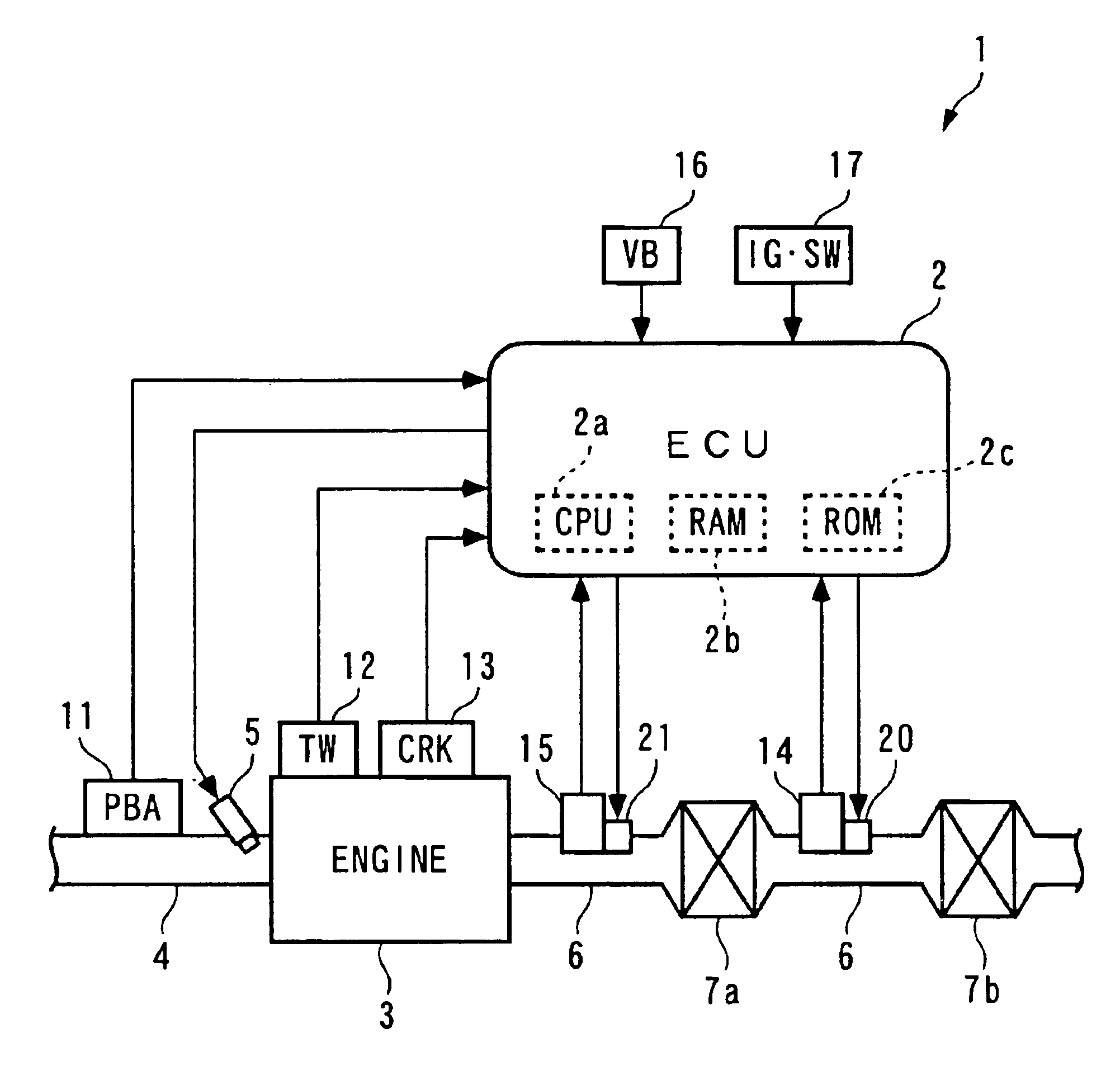
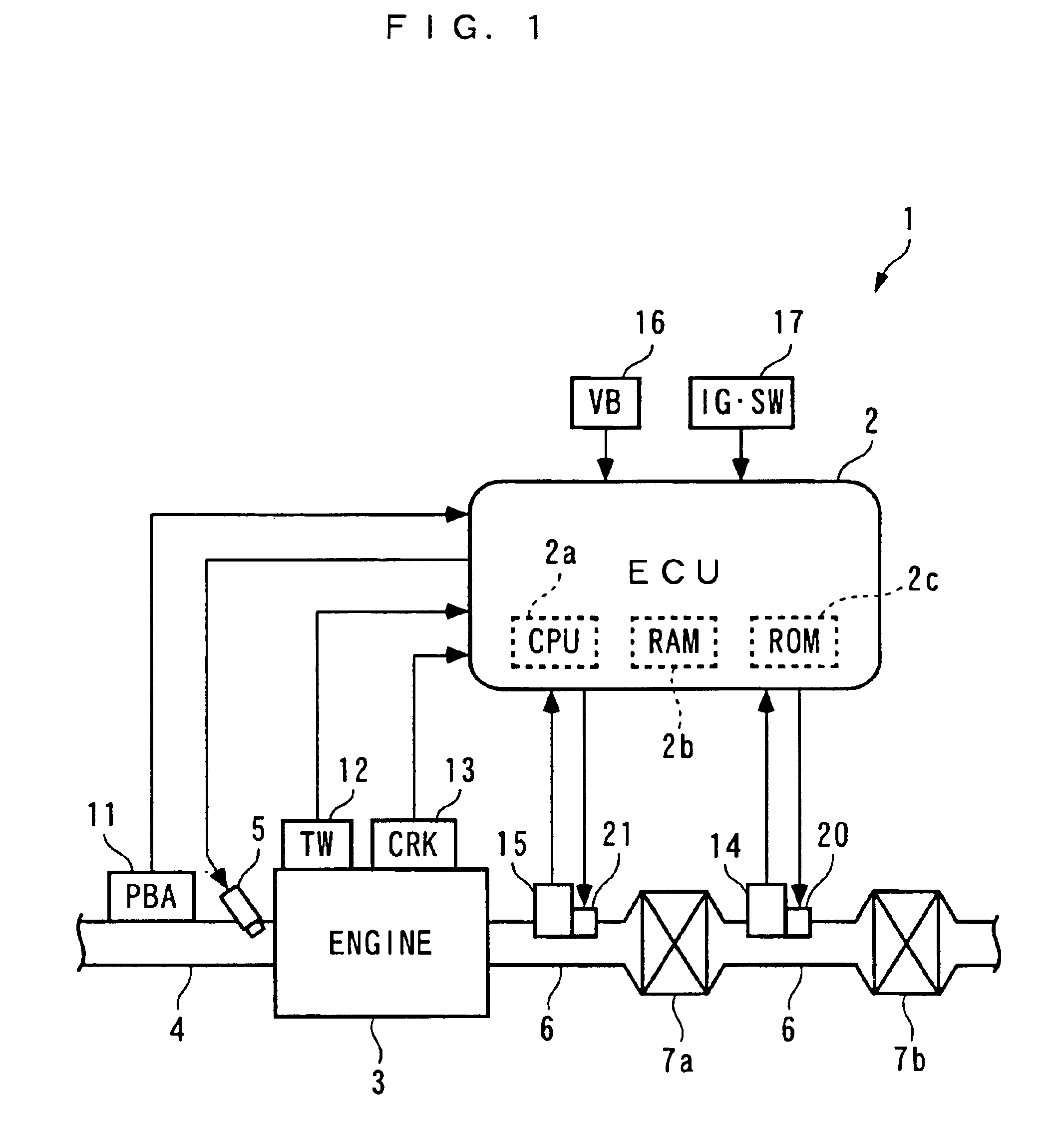
The present invention will now be described in detail with reference to the drawings showing an embodiment thereof. FIG. 1 schematically shows the arrangement of a control system according to an embodiment of the invention and an internal combustion engine provided with an oxygen concentration detector including a heater to which the control system is applied. As shown in FIG. 1, the control system 1 includes an ECU 2, which executes duty control of heaters 20 and 21, as described hereinafter.

The internal combustion engine (hereinafter simply referred to as “the engine”) 3 is a gasoline engine installed on a vehicle, not shown. The engine 3 has an intake pipe 4 having an intake pipe absolute pressure sensor 11 inserted therein at a location downstream of a throttle valve, not shown. The intake pipe absolute pressure sensor 11 is implemented e.g. by a semiconductor pressure sensor, which detects an intake pipe absolute pressure PBA within the intake pipe 4 and delivers an electric si...


PUM


Abstract

A control system capable of controlling a heater that heats an oxygen concentration detector in a fine-grained, efficient, and optimal manner. The control system controls an O2 heater for heating an O2 sensor provided in an exhaust pipe of an internal combustion engine, when the engine is started. An ECU sets a duty ratio of a control signal supplied to the O2 heater to a first predetermined value until a first predetermined time period has elapsed after the start of the engine was detected, and sets the same to a second predetermined value smaller than the first predetermined value until a second predetermined time period has elapsed after the lapse of the first predetermined value. Further, the ECU sets the duty ratio of the control signal to a third predetermined value smaller than the second predetermined value after the lapse of the second predetermined time period.

Description

BACKGROUND OF THE INVENTION1. Field of the InventionThe present invention relates to a control system and control method for controlling a heater that heats and activates an oxygen concentration detector provided in an exhaust passage of an internal combustion engine when the engine is started, as well as an engine control unit.2. Description of the Related ArtConventionally, a control system of the above-mentioned kind has been disclosed e.g. in Japanese Laid-Open Patent Publication (Kokai) No. H11-218044. In the control system, during the start of an internal combustion engine, a heater for heating an oxygen concentration sensor as an oxygen concentration detector is duty-controlled in two stages as described hereinbelow. More specifically, the duty ratio of a control signal to be inputted to the heater is held at a maximum value (100%) until a predetermined time period has elapsed after turn-on of an ignition switch (hereinafter referred to as “the IG·SW”). The reason for this is...

Claims


Application Information

Patent Timeline
IPC IPC(8): F02D41/14F01N7/00F01N7/02F01N13/02G01N27/409F02D45/00
CPCF01N3/101F02D41/1494F01N13/009F01N13/0093F02D41/1454F02D41/1456F02D2200/0406F02D2200/503Y02T10/22F02D2041/2027Y02T10/12
Inventor TOYOSHIMA, HIROKAZUESAKI, TATSUHITO
Owner HONDA MOTOR CO LTD
Why Eureka
Try Eureka