Laser doppler anemometry with diffractive optical elements

a technology of optical elements and laser diodes, applied in the field of laser diodes anemometry, can solve the problems of large temperature dependence of laser diodes, large weight of conventional lda systems, and uncertainty in velocity estimation, etc., and achieves the effects of low cost, maximum efficiency, and large scal

Inactive Publication Date: 2005-02-22
KAMSTRUP
View PDF12 Cites 8 Cited by
  • Summary
  • Abstract
  • Description
  • Claims
  • Application Information

AI Technical Summary

Benefits of technology

The first and second diffractive members may be diffraction gratings having substantially identical grating constants. In a preferred embodiment, the diffraction gratings are implemented as surface relief gratings. Such surface relief gratings may be manufactured in a large scale and low cost production facility using techniques such as injection moulding.
The diffraction gratings in combination may diffract the incoming light beam in such a way that approximately 50% of the intensity of the incoming light beam is contained in the undiffracted light beam from the first diffractive member, and that approximately 50% of the intensity of the incoming light beam is contained in the light beam diffracted from the second diffractive member. In this way maximum efficiency is obtained.

Problems solved by technology

The use of such bulky laser systems makes conventional LDA systems rather bulky and expensive in terms of manufacturing.
However, the emission wavelength of laser diodes is significant temperature dependent and even temperature stabilised laser diodes will be undefined within 1-3 longitudinal modes due to mode hops and hysteresis in the temperature dependence.
Since the measured frequency and thereby also the estimated velocity is directly proportional to the fringe spacing, the measured frequency for a given velocity will vary with the wavelength and will thus yield uncertainties in the estimation of the velocity.
A disadvantage of the system of U.S. Pat. No. 4,948,257 is that the closing angle of the beams in the measurement volume must be equal to the closing angle of the grating used as the beamsplitter.
This results in strong limitations on the obtainable fringe spacing in the measurement volume and the physical dimension of the optical system cannot be less than the working distance (distance from last optical element to the measurement volume).
However, the additional prisms increases the complexity and cost of manufacturing of the system of U.S. Pat. No. 4,948,257.
Furthermore, in one of the embodiments the position of the measurement volume will strongly depend on the wavelength which is undesirable.
In addition, no optical receiver system for collecting the scattered light has been devised and the optimal back-scatter receiver will be difficult to implement.
Thus, in the system of WO 00 / 19212 the grating and lens set a strong limitation of the obtainable fringe period in the measurement volume.
Such modification will add to the complexity and cost of the system suggested in WO 00 / 19212.
It is not possible to replicate such multiplexed volume holograms in a large scale low cost production.
However, using such surface relief gratings in the LDV suggested by J. Schmidts et al. would make the overall system efficiency much lower than the 75% obtained using volume holograms.
This is due to the fact that is not possible to realise high diffraction efficiencies of surface relief gratings with the small diffraction angles and grating frequencies used here.

Method used


Image

  • Laser doppler anemometry with diffractive optical elements
  • Laser doppler anemometry with diffractive optical elements
  • Laser doppler anemometry with diffractive optical elements

Examples


Embodiment Construction

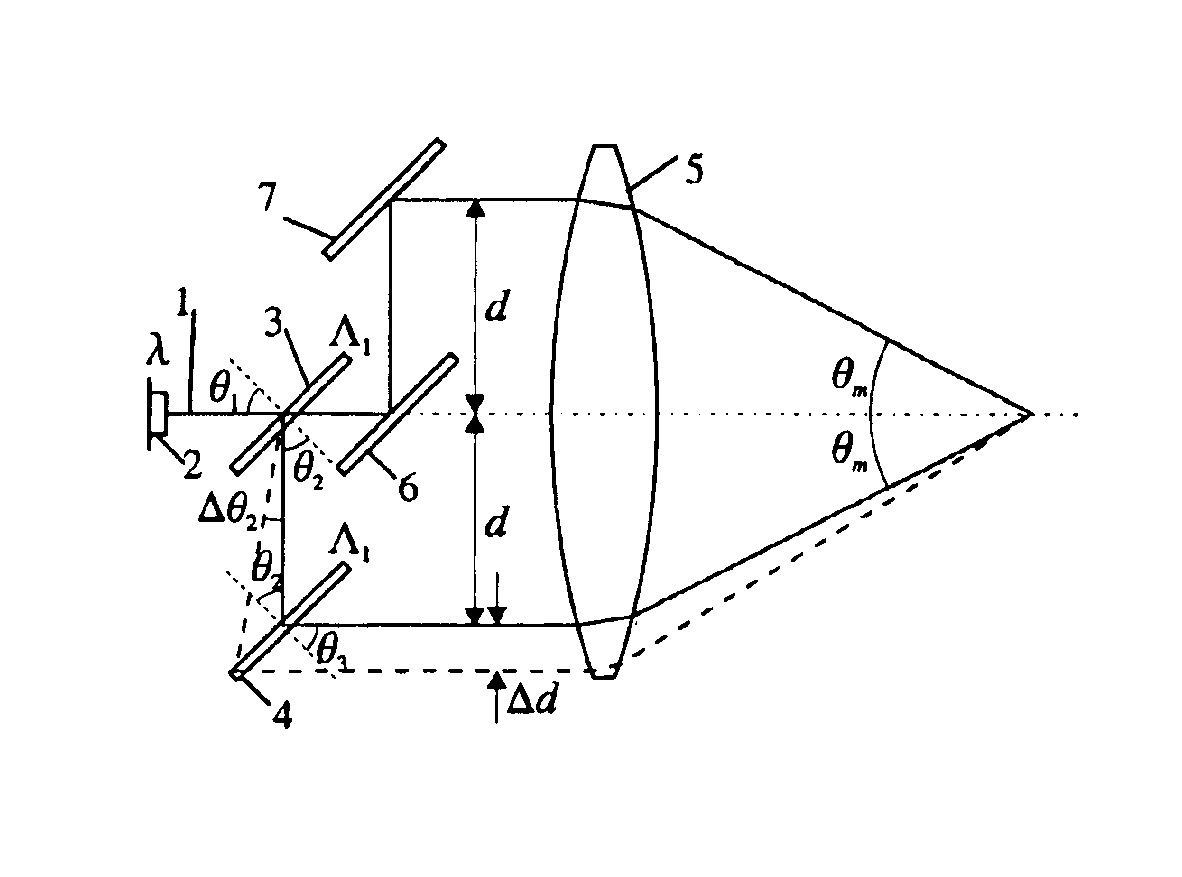
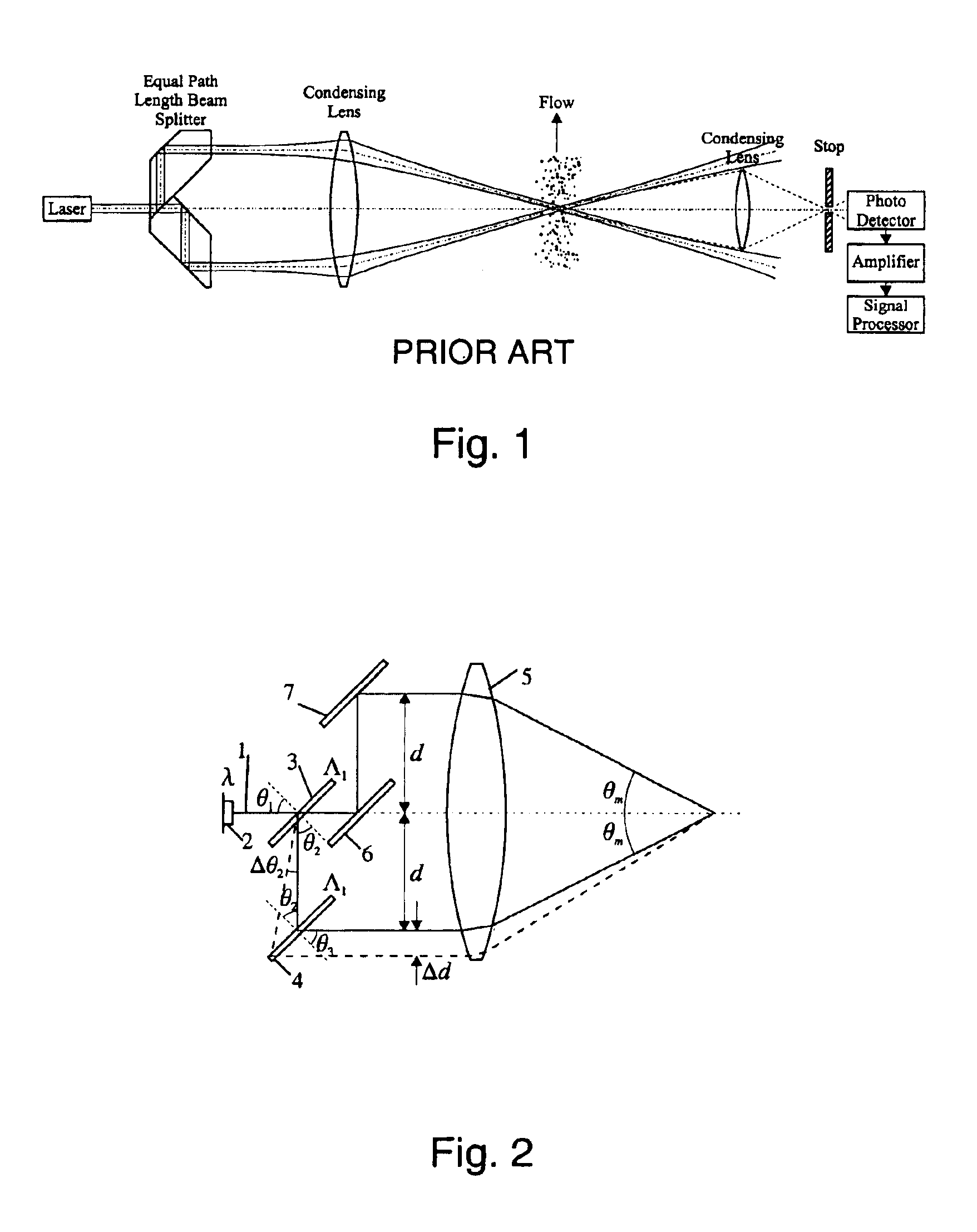
The LDA system according to the present invention is schematically illustrated in FIG. 2. A collimated laser beam 1, originating from a laser diode 2 with a collimation lens is incident on a linear grating 3 at an angle of 45 degrees to the normal. The grating both diffracts and transmits the light. The diffracted light is sent to another grating 4 with the same period. Thereby the light diffracted from the second grating 4 will be co-parallel with the transmitted light from the first grating 3. The light from these two “arms” is then sent to a condensing lens 5, which focuses and crosses the two laser beams at their beam waists. The result is that a fringe pattern arises in the section where the two beams are overlapping. The transmitted light from the first grating 3 is reflected in two mirrors 6,7 in order to assure an equal path length in the two arms.

The gratings are implemented as transmission surface relief gratings in photoresist. They are produced using an analog interferom...


PUM

PropertyMeasurementUnit
quasi-elastic interactionaaaaaaaaaa
wavelengthaaaaaaaaaa
distanceaaaaaaaaaa

Abstract

The present invention relates to an apparatus for use in the determination of a condition or state of an object based on quasi-elastic interaction between the object and light transmitted to the object, the apparatus comprising a beam splitter arrangement for splitting an incoming light beam of wavelength, λ, into a diffracted light beam and an undiffracted light beam, the beam splitter arrangement comprising a first and a second diffractive member, the first diffractive member transforming the light beam emitted by the light source into the diffracted and the undiffracted light beams, the second diffractive member receiving the diffracted light beam and diffracting the received light beam in a direction substantially parallel to the undiffracted light beam from the first diffractive member, wherein the diffracted light beam, after being diffracted by the second diffractive member, and the undiffracted light beam from the first diffractive member are separated by a distance, d, said distance, d, being dependent on wavelength, λ.

Description

FIELD OF THE INVENTIONThe present invention relates to a Laser Doppler Anemometry (LDA) system, which assures that the fringe spacing in a measurement volume is independent of wavelength changes, whereby non-stabilised laser diodes may be applied as light sources.BACKGROUND OF THE INVENTIONThe most widely used optical technique for measurement of velocity of fluid flow or solid objects known in the art is the laser Doppler technique. According to this technique, two laser beams from the same laser are set to intersect at their beam waists. This region is referred to as the measurement volume. Scattered light from particles passing this region is imaged onto a photo detector. Since the light scattered from both beams reaches the detector simultaneously, a beat frequency, corresponding to the difference in Doppler shifts from the two scattered beams, is obtained. The beat frequency is directly proportional to the velocity component perpendicular to the fringe geometry, which emerges i...

Claims


Application Information

Patent Timeline
Patent Type & Authority Patents(United States)
IPC IPC(8): G01P5/26G01P5/00G01S17/58G01S17/00G01P15/18
CPCG01P5/26G01P15/18G01S17/58
Inventor DAM-HANSEN, CARSTENKITCHEN, STEVEN RICHARDJAKOBSEN, MICHAEL LINDE
Owner KAMSTRUP
Why Eureka
Try Eureka