
Transpinnor-based transmission line transceivers and applications

Inactive Publication Date: 2005-02-22
INTEGRATED MAGNETOELECTRONICS
View PDF22 Cites 24 Cited by
  • Summary
  • Abstract
  • Description
  • Claims
  • Application Information

AI Technical Summary

Problems solved by technology

However, the precision of such techniques appears to be approaching its limit, making it unlikely that systems manufactured according to such technique will be able to continue their historical adherence to Moore's Law which postulates a monotonic increase in available data processing power over time.
In addition, as the techniques for manufacturing semiconductor integrated circuits have increased in sophistication, so have they correspondingly increased in cost.
For example, current state-of-the-art integrated circuits require a large number of processing steps to integrate semiconductor circuitry, metal layers, and embedded circuits, an issue which is exacerbated by the varied nature of the materials being integrated.
And the demand for higher levels of complexity and integration continue to grow.
Finally, there are some applications for which conventional semiconductor integrated circuit technology is simply not well suited.
Not only are these measures costly in terms of dollars and weight, they are not always completely effective, an obvious drawback given the dangers of space travel.

Method used


Image

  • Transpinnor-based transmission line transceivers and applications
  • Transpinnor-based transmission line transceivers and applications
  • Transpinnor-based transmission line transceivers and applications

Examples


Embodiment Construction

Reference will now be made in detail to specific embodiments of the invention including the best modes contemplated by the inventors for carrying out the invention. Examples of these specific embodiments are illustrated in the accompanying drawings. While the invention is described in conjunction with these specific embodiments, it will be understood that it is not intended to limit the invention to the described embodiments. On the contrary, it is intended to cover alternatives, modifications, and equivalents as may be included within the spirit and scope of the invention as defined by the appended claims. In the following description, numerous specific details are set forth in order to provide a thorough understanding of the present invention. The present invention may be practiced without some or all of these specific details. In addition, well known process operations have not been described in detail in order not to unnecessarily obscure the present invention.

“Giant magnetoresi...


PUM


Abstract

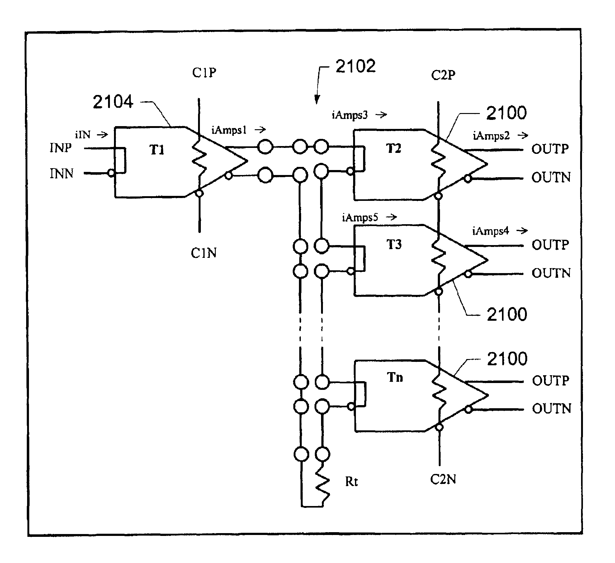
Transceiver components for a transmission line are described. A driver includes a first network of thin-film elements exhibiting giant magnetoresistance, and a first input conductor inductively coupled to at least one of the thin-film elements in the first network. At least one dimension of each thin-film element in the first network is configured with reference to the characteristic impedance of the transmission line. A receiver includes a second network of thin-film elements exhibiting giant magnetoresistance, and a second input conductor inductively coupled to at least one of the thin-film elements in the second network. A termination impedance in series with the second input conductor has a value relating to the characteristic impedance of the transmission line.

Description

BACKGROUND OF THE INVENTIONThe present invention relates to circuits and systems incorporating solid-state devices referred to herein as “transpinnors” and described in U.S. Pat. No. 5,929,636 and 6,031,273, the entire disclosures of which are incorporated herein by reference for all purposes. More specifically, the present application describes transpinnor-based transmitters and receivers for facilitating the reliable transmission of information via transmission lines and various applications thereof.The vast majority of electronic circuits and systems manufactured and sold today are based on semiconductor technology developed over the last half century. Semiconductor processing techniques and techniques for manufacturing integrated circuits have become increasingly sophisticated resulting in ever smaller device size while increasing yield and reliability. However, the precision of such techniques appears to be approaching its limit, making it unlikely that systems manufactured acc...

Claims


Application Information

Patent Timeline
IPC IPC(8): H03F15/00H04L25/02
CPCH03F15/00H04L25/0292H04L25/028H04L25/0278H04L25/0272
Inventor NUSPL, STEPHEN J.WUORI, EDWARDTOROK, E. JAMES
Owner INTEGRATED MAGNETOELECTRONICS
Learn More